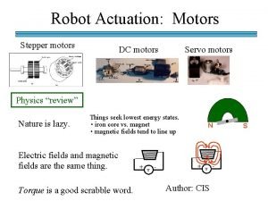
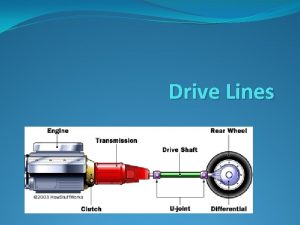
F I R S T Motors Drive System


![Design Condition Continued O. K. So what is my top speed? Vmax [m/sec] = Design Condition Continued O. K. So what is my top speed? Vmax [m/sec] =](https://slidetodoc.com/presentation_image_h/cfbbf2e2c5f7e0b575ed9c8e12957cfc/image-29.jpg)


- Slides: 31

F. I. R. S. T. Motors & Drive System Design January 4 th, 2003 FIRST Novi Kickoff Paul Copioli Utica Community Schools & Ford Motor Company The Thunder. Chickens (Team #217) page 1

Agenda 1. Introduction (why we are here) 2. Intro to Things Mechanical 3. First Motor Characteristics 4. Robot Drive Systems - Design Objectives 5. Questions & Answers page 2

Introduction Who am I? • Paul Copioli • Bachelors of Science - Aeronautical Engineering • U. S. Air Force Academy • M. S. E. - Aerospace & Mechanical Engineering • University of Michigan • FANUC Robotics North America • Senior Product Development Engineer • 4 th Season with FIRST page 3

Intro to Things Mechanical • • page 4 Force - units are Pounds (Lbf) & Newtons (N) Velocity - meters/sec, ft/sec, MPH Acceleration - m/s 2, ft/s 2, g = 9. 81 m/s 2 Angular Velocity - RPM, rad/sec, deg/sec Torque - N*m, ft*Lbf Torque = Force * Lever Arm (Wheel Radius) Velocity = Ang. Velocity * Wheel Radius

Formulas & Units • Unit conversions of interest – – – 1 lbs = 4. 45 N 1 inch = 0. 0254 meters 1 in-lbs = 0. 11 N-m 1 RPM = 60 Rev / Hour = 0. 105 Rad / Sec 1 mile = 5280 X 12 inches = 63, 000 inches • Power = Force (N) X Velocity (m/s) • Power = Torque (N-m) X Angular Velocity (Rad/Sec) • Electrical Power = Voltage X Current page 5

FIRST Motors 1. Motor Characteristics (Motor Curve) 2. Max Power vs. Power at 30 Amps 3. Motor Comparisons 4. Combining Motors page 6

• Torque v Speed Curves – Stall Torque (T 0) – Stall Current (A 0) – Free Speed (Wf) – Free Current (Af) Torque, Current Motor Characteristics T 0 Af Speed page 7 K (slope) Wf

• • Y=Motor Torque m=K (discuss later) X=Motor Speed b=Stall Torque (T 0) Torque, Current Slope-Intercept (Y=m. X + b) T 0 K (slope) A 0 Af Speed Wf What is K? … It is the slope of the line. Slope = change in Y / change in X = (0 - T 0)/(Wf-0) = -T 0/Wf K = Slope = -T 0/Wf page 8

• • Y=Motor Torque m=K = -T 0/Wf X=Motor Speed b=Stall Torque = T 0 Torque, Current (Y=m. X + b) Continued. . . T 0 (b) K (-T 0/Wf) A 0 Af Speed Equation for a motor: Torque = (-T 0/Wf) * Speed + T 0 page 9 Wf

• What are cutoff Amps? – Max useable amps – Limited by breakers – Need to make assumptions Torque, Current (Amps) and FIRST T 0 A 0 Cutoff Amps Speed Can our Motors operate above 30(40) amps? Af Wf - Absolutely, but not continuous. When designing, you want to be able to perform continuously; so finding motor info at 30 (40) amps could prove to be useful. page 10

• T 30 = Torque at 30(40) Amps • W 30 = Speed at 30(40) Amps Current Equation: Current = (Af-A 0)/Wf * Speed + A 0 Torque, Current Torque at Amp Limit T 0 A 0 Cutoff Amps Af Motor Equation: Torque = (-T 0/Wf) * Speed + T 0 S @ 30 A (W 30) = (30 - A 0) * Wf / (Af-A 0) T @ 30 A (T 30) = (-T 0/Wf) * W 30 + T 0 page 11 Speed Wf Use 40 Amps for 2003 Drill & Chiaphua

Power = Torque * Speed Must give up torque for speed Max Power occurs when: T = T 0/2 & W=Wf/2 What if max power occurs at a current higher than 30 A (40 A)? Torque, Current Power - Max vs. 30(40) Amps Power T 0 Af Speed Wf Paul’s Tip #1: Design drive motor max power for 30 A(40 A)! Power is Absolute - It determines the Torque Speed tradeoff! page 12

Motor Comparisons Let’s Look at Some FIRST Motors • Chiaphua Motor • Drill Motor • Johnson Electric Fisher-Price Motor We will compare T 0, Wf, A 0, Af, T 30, W 30, max power (Pmax), amps @ max power (Apmax), and power at 30(40) amps (P 30). We will be using Dr. Joe’s motor spreadsheet updated to handle the new motors. page 13

Motor Comparisons Motor Equations: 1. 2003 Fisher-Price: T = (-0. 38/15, 000) * W + 0. 38 2. 2003 Bosch Drill: T = (-0. 87/19, 670) * W + 0. 87 3. 2002 -03 Chiaphua: T = (-2. 2/5, 500) * W + 2. 2 page 14

Combining Motors Using multiple motors is common for drive trains. We will look at matching the big 3 motors. I try to match at free speed, but you can match at any speed you like!! Wf Drill/Wf FP 19670/15000 ~ 17/13 = Gear Ratio Wf drill / Wf Chiaphua = 19670/5500 ~ 18/5 = Gear Ratio Wf FP / Wf Chiaphua = 15000/5500 ~ 30/11 = Gear Ratio We will use an efficiency of 95% for the match gears. More to come on Gear Ratio & Efficiency in the Second Half! page 15

Combined Motor Data Motor Equations: 1. F-P & Drill: T = (-1. 46/15, 000) * W + 1. 46 2. F-P & Chip: T = (-3. 19/5, 500) * W + 3. 19 3. Drill & Chip: T = (-5. 18/5, 479) * W + 5. 18 4. F-P, Drill, & Chip: T = (-6. 16/5, 483) * W + 6. 16 page 16

Motor Q & A page 17

Robot Drive Systems 1. Drive System Terms 2. Types of Mechanisms 3. Traction Basics 4. Gearing Basics 5. Design Condition page 18

Drive System Terms 1. Gear Ratio: Can be described many ways - Motor Speed / Output Speed 2. Efficiency - Work lost due to drive losses - Friction, heat, misalignment 3. Friction Force - Tractive (pushing) force generated between floor and wheel. 4. W is rotational speed & V is linear Speed (velocity) 5. N 1 is # of teeth on input gear/sprocket 6. N 2 is # of teeth on output gear/sprocket page 19

Types of Drive Mechanisms 1. Chain & Belt Efficiency ~ 95% - 98% GR = N 2/N 1 N 2 N 1 2. Spur Gears Efficiency ~ 95% - 98% GR = N 2/N 1 page 20 N 2

Types of Drive Mechanisms 3. Bevel Gears Efficiency ~ 90% - 95% GR = N 2/N 1 N 2 page 21

Types of Drive Mechanisms 4. Worm Gears Efficiency ~ 40% - 70% # Teeth on Worm Gear GR = ---------------# of Threads on worm Worm gear page 22

Types of Drive Mechanisms 5. Planetary Gears Efficiency ~ 80% - 90% RING GEAR (FIXED) SUN GEAR (INPUT) CARRIER (OUTPUT) PLANET GEAR Nring GR = ------- + 1 Nsun page 23

Traction Basics • Remember Ken Patton’s Key Points • Ffriction = m * Fnormal • Experimentally determine m: • Fnormal = Weight * cos(q) n • Fparallel = Weight * sin(q) o i t c Ffri l e l l a ar Fp q m = sin(q) / cos(q) page 24 m = tan(q) al orm Fn When Ff = Fp, no slip Ff = m*Weight * cos(q) Fp = Weight * sin(q) = m*Weight * cos(q) Weight

Gearing Basics • Consecutive gear stages multiply: N 2 N 4 N 1 N 3 • Gear Ratio is (N 2/N 1) * (N 4/N 3) • Efficiency is. 95 *. 95 =. 90 page 25

Gearing Basics - Wheel Attachment N 2 N 1 Motor Shaft N 4 Wheel Diameter - Dw Dw = Rw * 2 N 3 Fpush • Gear 4 is attached to the wheel • Remember that T = F * Rw • Also, V = W * Rw • T 4 = T 1 * N 2/N 1 * N 4/N 3 *. 95 • W 4 = W 1 * N 1/N 2 * N 3/N 4 • F = T 4 / Rw • V = W 4 * Rw page 26

Design Condition • Assumptions • Each of the 4 wheels have their own motor. • Weight is evenly distributed. • Using all spur gears. • Terms • W = Weight of robot • Wt = Weight transferred to robot from goals • n = # of wheels on the ground (4) • p = # driving wheels per transmission (1) • q = # of transmissions (4) • Tout = wheel output Torque • Find the gear ratio & wheel diameter to maximize push force. The maximum force at each wheel we can attain is ? ? ? Fmax = Ffriction = Mu*(W + Wt)/n Now T = F * Rw ----> F = Tout / Rw page 27 {on a flat surface}

Design Condition Continued • Tout = T 30(40) * GR * eff {@ each wheel} Ffriction = Tout / Rw: Mu*(W + Wt)/n = T 30(40) * GR * eff / Rw Mu*(W + Wt) GR/Rw = -------------n*T 30(40)*eff The above gives you the best combination of gear ratio and wheel diameter for maximum pushing force! page 28
![Design Condition Continued O K So what is my top speed Vmax msec Design Condition Continued O. K. So what is my top speed? Vmax [m/sec] =](https://slidetodoc.com/presentation_image_h/cfbbf2e2c5f7e0b575ed9c8e12957cfc/image-29.jpg)
Design Condition Continued O. K. So what is my top speed? Vmax [m/sec] = 0. 9 * Wfree * p * 2 * Rw ---------------60 * GR Where Wfree is in RPM, Rw is in meters. The 0. 9 accounts for drive friction slowing the robot down. page 29

Design Condition Continued 0. 9 * Wfree * p * 2 * Rw 0. 9 * Wfree * p * 2 * n * T 30 * eff Vmax = --------------------------------------60 * GR 60 * Mu * (W + Wt) T 30 * GR * eff Fmax = ---------- = Mu * (W + Wt) Rw Max force and max velocity are fighting each other page 30

Drive System Fundamentals QUESTIONS? page 31
 Understanding google drive
 Slidetodoc.com
 гугл диск
 Cross belt drive
 1https://drive.google.com/drive/u/1
 Http drive google com
 Difference between chain drive and belt drive
 Comait
 Lisa gue
 Wheel hub motors for automotive applications
 How to program a dts gate motor
 Lesson 6 dc generators and motors
 Jaguar swot analysis
 Mashima motors and gearboxes
 Induction motors procurement
 Podium motors
 General motors organizational structure
 Agv stepper motors
 General motors company profile
 How does a electric motor work
 Tata motors founded
 What are engineered plans for motors pumps
 Special purpose motors
 Step motors and control systems
 Annajah motors
 Annajah motors
 Advanced dc motors
 Abb motors and generators
 Nccer introduction to construction drawings
 Test single phase motor
 Unit 18 application of motors
 Scott dc motors


