Evaluation of LNG Production Technologies Ayema Aduku Oluwaseun


- Slides: 43
Evaluation of LNG Production Technologies Ayema Aduku Oluwaseun Harris Valerie Rivera Miguel Bagajewicz University of Oklahoma
Outline LNG Background n Objective n Simulation Specifications n Liquefaction Techniques n Heat Exchanger Types n Simulation Method n Results n
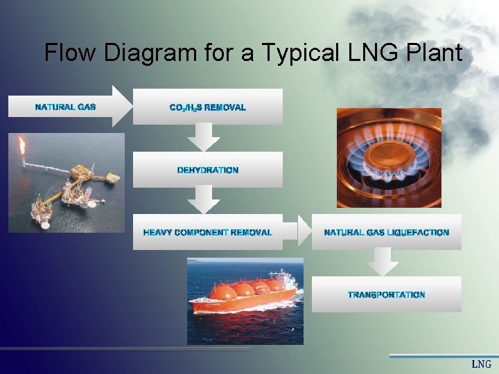
Flow Diagram for a Typical LNG Plant
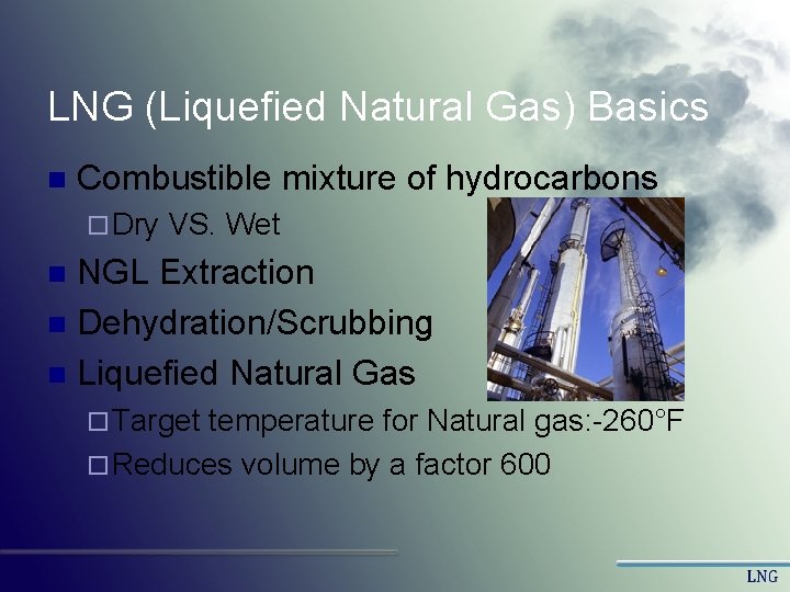
LNG (Liquefied Natural Gas) Basics n Combustible mixture of hydrocarbons ¨ Dry VS. Wet NGL Extraction n Dehydration/Scrubbing n Liquefied Natural Gas n ¨ Target temperature for Natural gas: -260°F ¨ Reduces volume by a factor 600
Objective n Main Objectives ¨ Simulate Processes ¨ Optimize Processes n Minimize compressor work ¨ Compare Processes based on n Capital cost n Energy cost n Total cost per capacity(Ton)
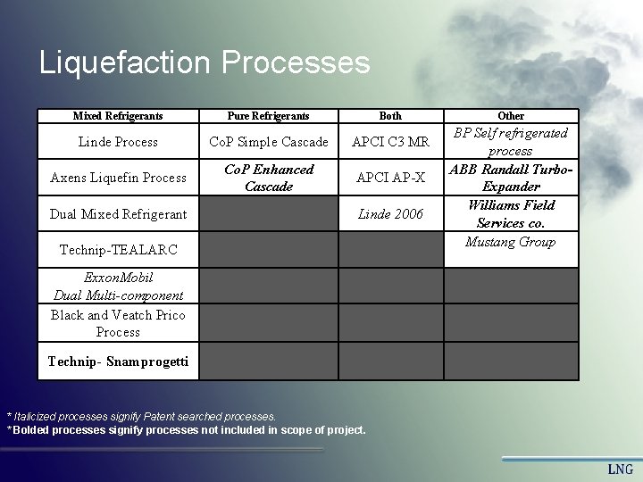
Liquefaction Processes Mixed Refrigerants Pure Refrigerants Both Linde Process Co. P Simple Cascade APCI C 3 MR Axens Liquefin Process Co. P Enhanced Cascade APCI AP-X Dual Mixed Refrigerant Linde 2006 Technip-TEALARC Exxon. Mobil Dual Multi-component Black and Veatch Prico Process Technip- Snamprogetti * Italicized processes signify Patent searched processes. * Bolded processes signify processes not included in scope of project. Other BP Self refrigerated process ABB Randall Turbo. Expander Williams Field Services co. Mustang Group
Flow diagrams
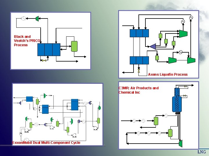
Black and Veatch’s PRICO Process Axens Liquefin Process C 3 MR: Air Products and Chemical Inc Exxon. Mobil Dual Multi-Component Cycle
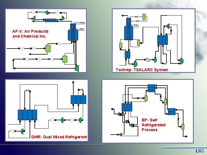
AP-X: Air Products and Chemical Inc. Technip- TEALARC System BP- Self Refrigerated Process DMR- Dual Mixed Refrigerant
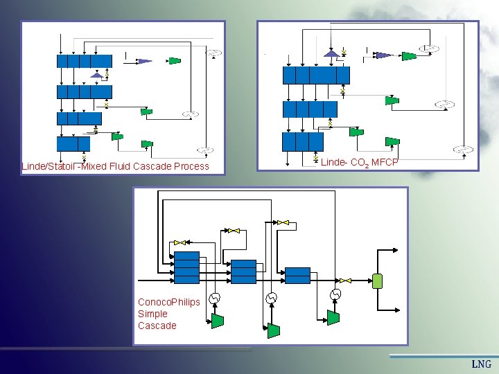
Linde/Statoil -Mixed Fluid Cascade Process Conoco. Philips Simple Cascade Linde- CO 2 MFCP
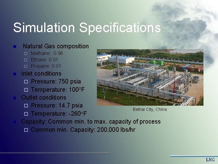
Simulation Specifications n Natural Gas composition Methane: 0. 98 ¨ Ethane: 0. 01 ¨ Propane: 0. 01 ¨ n n n Inlet conditions ¨ Pressure: 750 psia ¨ Temperature: 1000 F Outlet conditions ¨ Pressure: 14. 7 psia Beihai City, China o ¨ Temperature: -260 F Capacity: Common min. to max. capacity of process ¨ Common min. Capacity: 200, 000 lbs/hr
Liquefaction Techniques n Different Liquefaction techniques include: ¨ Single Refrigeration cycle ¨ Multiple Refrigeration cycles ¨ Self Refrigerated cycles ¨ Cascade Processes n The cooling of natural gas involves the use of refrigerants which could either be pure component refrigerants or mixed component refrigerants.
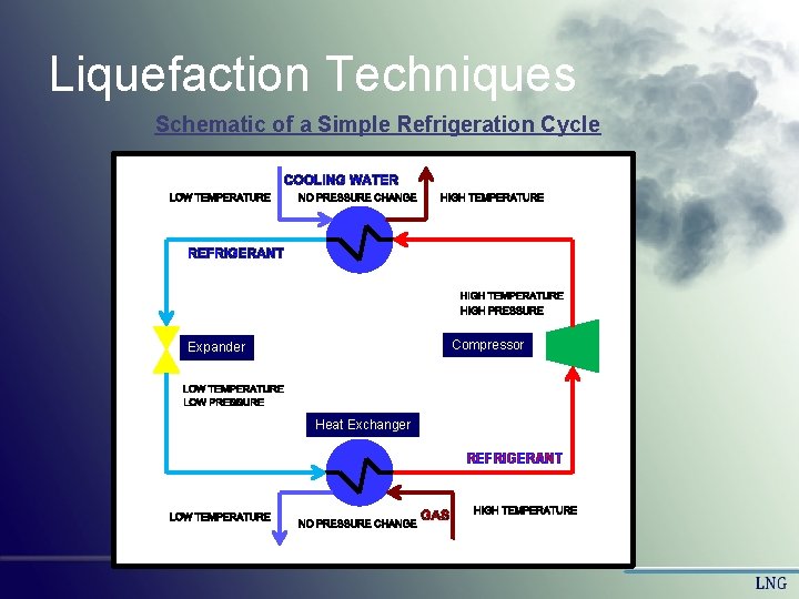
Liquefaction Techniques Schematic of a Simple Refrigeration Cycle Compressor Expander Heat Exchanger REFRIGERANT
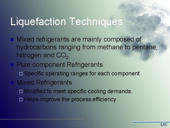
Liquefaction Techniques n n Mixed refrigerants are mainly composed of hydrocarbons ranging from methane to pentane, Nitrogen and CO 2. Pure component Refrigerants ¨ Specific operating ranges for each component n Mixed Refrigerants ¨ Modified to meet specific cooling demands. ¨ Helps improve the process efficiency
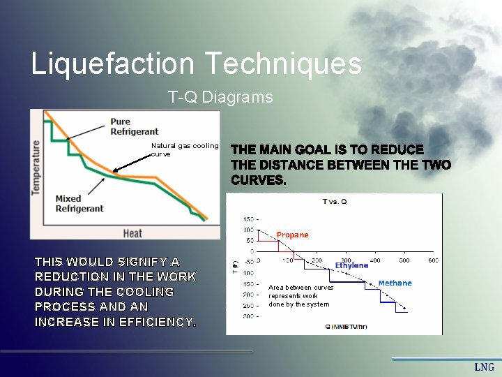
Liquefaction Techniques T-Q Diagrams Natural gas cooling curve THIS WOULD SIGNIFY A REDUCTION IN THE WORK DURING THE COOLING PROCESS AND AN INCREASE IN EFFICIENCY. Area between curves represents work done by the system
Liquefaction Techniques Single Refrigeration Cycle ¨ One refrigeration loop that cools the natural gas to its required temperature range. ¨ Usually requires fewer equipment and can only handle small base loads. ¨ Lower capital costs and a higher operating efficiency
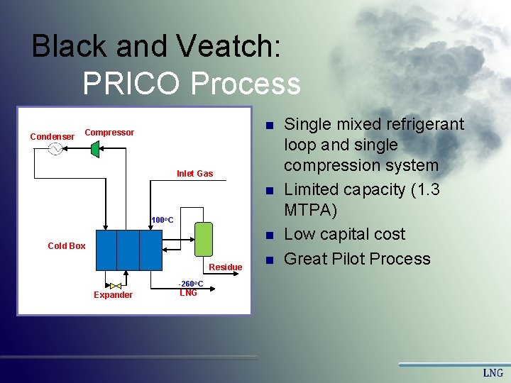
Black and Veatch: PRICO Process Condenser n Compressor Inlet Gas n 100 o. C n Cold Box Residue -260 o. C Expander LNG n Single mixed refrigerant loop and single compression system Limited capacity (1. 3 MTPA) Low capital cost Great Pilot Process
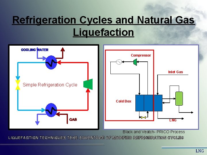
Refrigeration Cycles and Natural Gas Liquefaction Compressor Inlet Gas Simple Refrigeration Cycle Cold Box LNG Black and Veatch- PRICO Process LIQUEFACTION TECHNIQUES TAKE ADVANTAGE OF MODIFIED REFRIGERATION CYCLES
Liquefaction Techniques Multiple Refrigeration cycles ¨ Contains two or more refrigeration cycles. Refrigerants involved could be a combination of mixed or pure component refrigerants. ¨ Some cycles are setup primarily to supplement cooling of the other refrigerants before cooling the natural gas. ¨ More equipment usually involved to handle larger base loads.
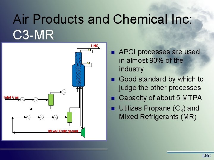
Air Products and Chemical Inc: C 3 -MR LNG n n n Inlet Gas n Mixed Refrigerant APCI processes are used in almost 90% of the industry Good standard by which to judge the other processes Capacity of about 5 MTPA Utilizes Propane (C 3) and Mixed Refrigerants (MR)
Liquefaction Techniques Self Refrigerated Cycles ¨ Takes advantage of the cooling ability of hydrocarbons available in the natural gas to help in the liquefaction process. ¨ Numerous expansion stages are required to achieve desired temperatures. ¨ Considered as a safer method because there are no external refrigerants needing storage.
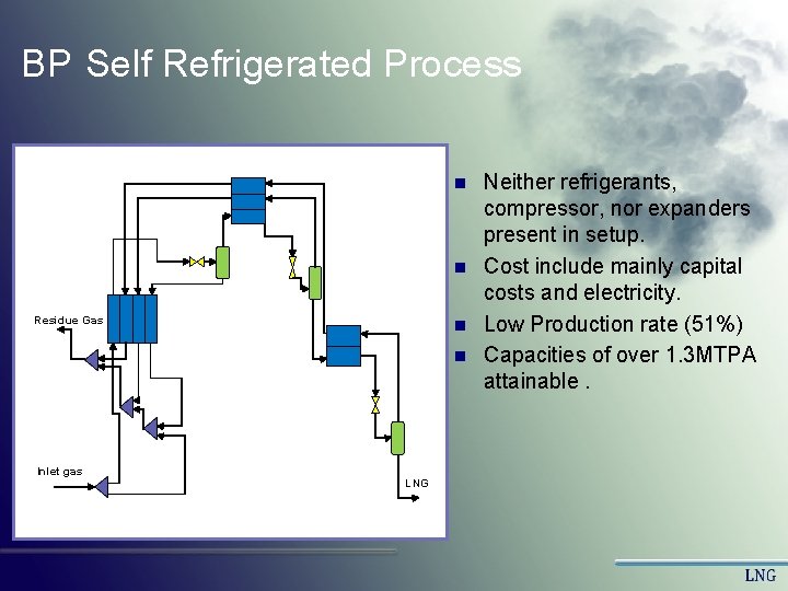
BP Self Refrigerated Process n n Residue Gas n n Inlet gas LNG Neither refrigerants, compressor, nor expanders present in setup. Cost include mainly capital costs and electricity. Low Production rate (51%) Capacities of over 1. 3 MTPA attainable.
Liquefaction Techniques Cascade Processes ¨ A series of heat exchangers with each stage using a different refrigerant. ¨ Tailored to take advantage of different thermodynamic properties of the refrigerants to be used. ¨ Usually have high capital costs and can handle very large base loads.
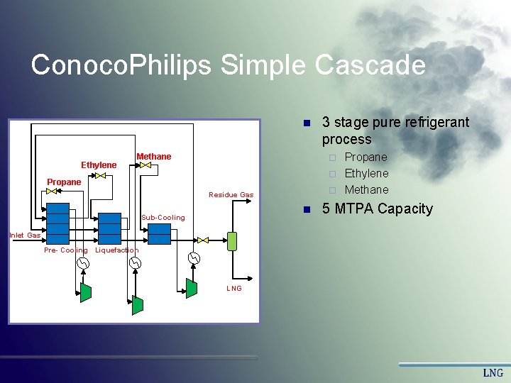
Conoco. Philips Simple Cascade n Ethylene 3 stage pure refrigerant process Propane ¨ Ethylene ¨ Methane ¨ Propane Residue Gas n Sub-Cooling Inlet Gas Pre- Cooling Liquefaction LNG 5 MTPA Capacity
Equipment
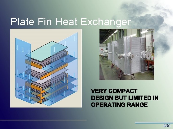
Plate Fin Heat Exchanger
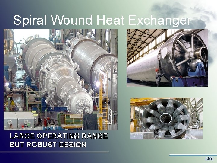
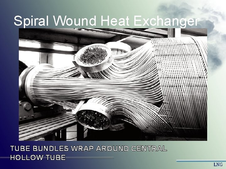
Spiral Wound Heat Exchanger LARGE OPERATING RANGE BUT ROBUST DESIGN
Spiral Wound Heat Exchanger TUBE BUNDLES WRAP AROUND CENTRAL HOLLOW TUBE
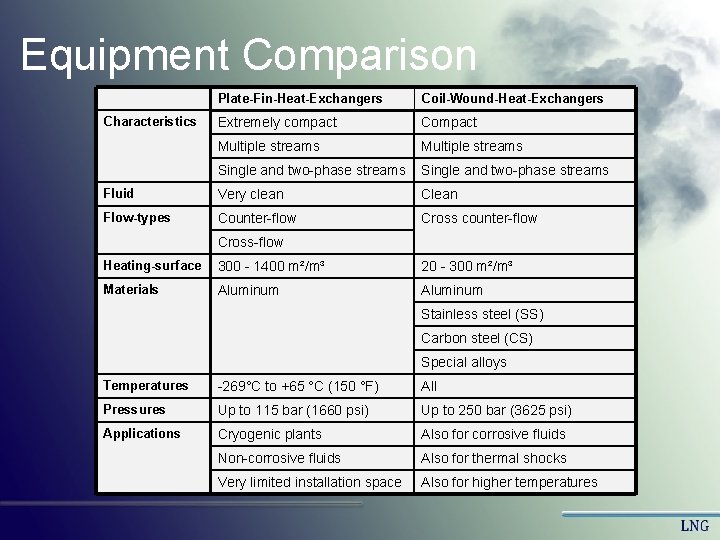
Equipment Comparison Plate-Fin-Heat-Exchangers Coil-Wound-Heat-Exchangers Characteristics Extremely compact Compact Multiple streams Single and two-phase streams Fluid Very clean Clean Flow-types Counter-flow Cross counter-flow Cross-flow Heating-surface 300 - 1400 m²/m³ 20 - 300 m²/m³ Materials Aluminum Stainless steel (SS) Carbon steel (CS) Special alloys Temperatures -269°C to +65 °C (150 °F) All Pressures Up to 115 bar (1660 psi) Up to 250 bar (3625 psi) Applications Cryogenic plants Also for corrosive fluids Non-corrosive fluids Also for thermal shocks Very limited installation space Also for higher temperatures
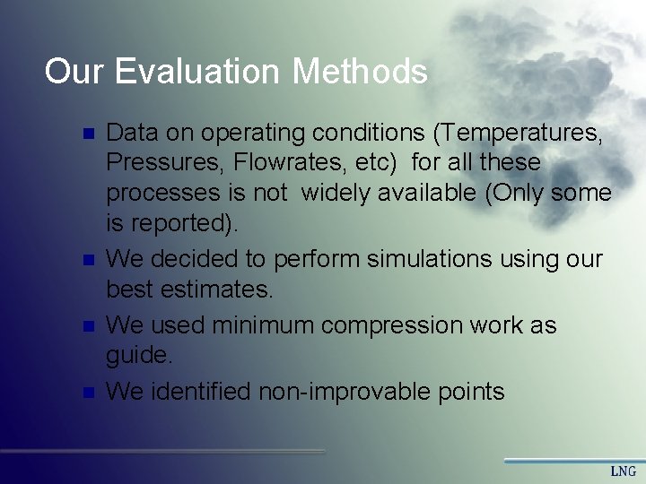
Our Evaluation Methods n n Data on operating conditions (Temperatures, Pressures, Flowrates, etc) for all these processes is not widely available (Only some is reported). We decided to perform simulations using our best estimates. We used minimum compression work as guide. We identified non-improvable points
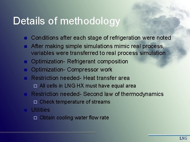
Details of methodology n n n Conditions after each stage of refrigeration were noted After making simple simulations mimic real process, variables were transferred to real process simulation Optimization- Refrigerant composition Optimization- Compressor work Restriction needed- Heat transfer area ¨ n Restriction needed- Second law of thermodynamics ¨ n All cells in LNG HX must have equal area Check temperature of streams Utilities ¨ Obtain cooling water flow rate
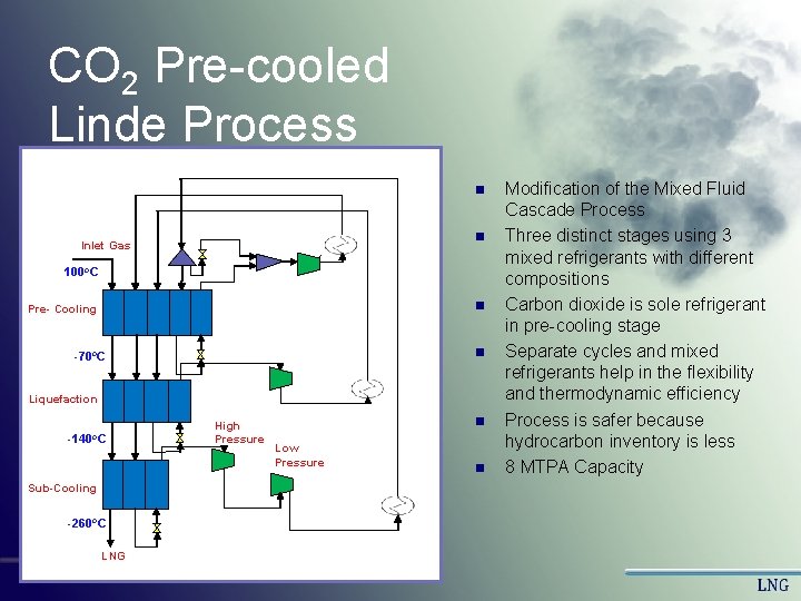
CO 2 Pre-cooled Linde Process n n Inlet Gas 100 o. C n Pre- Cooling n -70 o. C Liquefaction -140 o. C Sub-Cooling -260 o. C LNG High Pressure n Low Pressure n Modification of the Mixed Fluid Cascade Process Three distinct stages using 3 mixed refrigerants with different compositions Carbon dioxide is sole refrigerant in pre-cooling stage Separate cycles and mixed refrigerants help in the flexibility and thermodynamic efficiency Process is safer because hydrocarbon inventory is less 8 MTPA Capacity
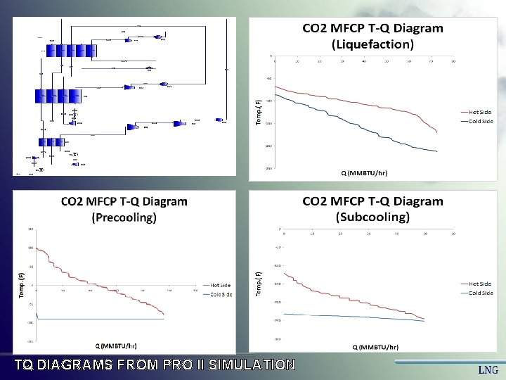
TQ DIAGRAMS FROM PRO II SIMULATION
Results
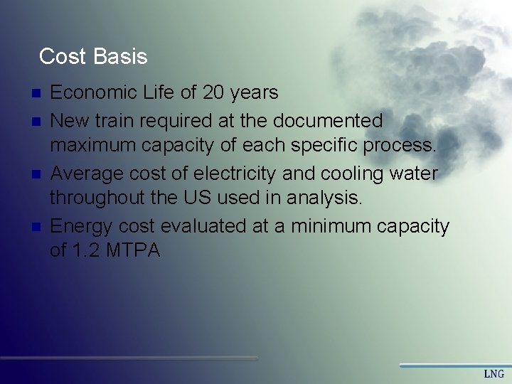
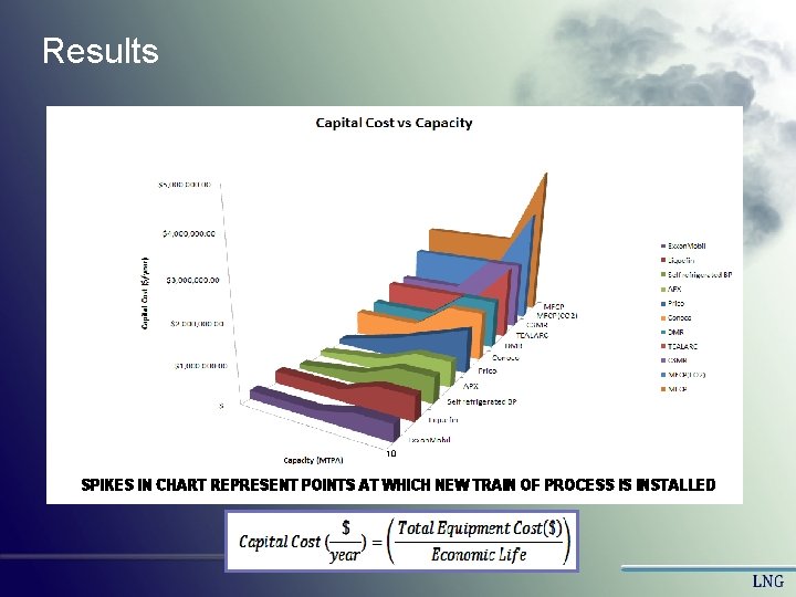
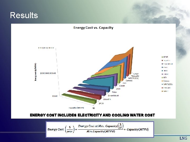
Cost Basis n n Economic Life of 20 years New train required at the documented maximum capacity of each specific process. Average cost of electricity and cooling water throughout the US used in analysis. Energy cost evaluated at a minimum capacity of 1. 2 MTPA
Results 10 SPIKES IN CHART REPRESENT POINTS AT WHICH NEW TRAIN OF PROCESS IS INSTALLED
Results 10 ENERGY COST INCLUDES ELECTRICITY AND COOLING WATER COST
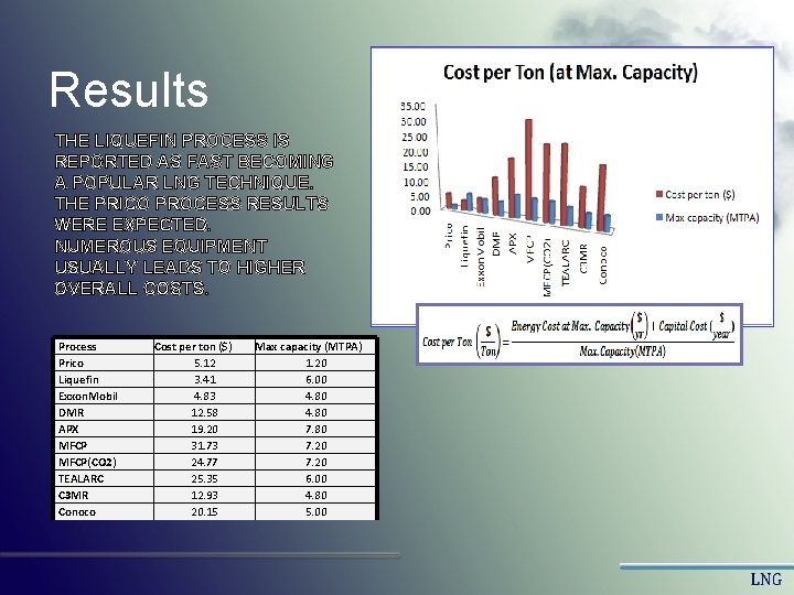
Results THE LIQUEFIN PROCESS IS REPORTED AS FAST BECOMING A POPULAR LNG TECHNIQUE. THE PRICO PROCESS RESULTS WERE EXPECTED. NUMEROUS EQUIPMENT USUALLY LEADS TO HIGHER OVERALL COSTS. Process Prico Liquefin Exxon. Mobil DMR APX MFCP(CO 2) TEALARC C 3 MR Conoco Cost per ton ($) 5. 12 3. 41 4. 83 12. 58 19. 20 31. 73 24. 77 25. 35 12. 93 20. 15 Max capacity (MTPA) 1. 20 6. 00 4. 80 7. 20 6. 00 4. 80 5. 00
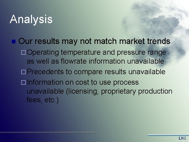
Analysis n Our results may not match market trends ¨ Operating temperature and pressure range as well as flowrate information unavailable ¨ Precedents to compare results unavailable ¨ Information on cost to use process unavailable (licensing, proprietary production fees, etc. )
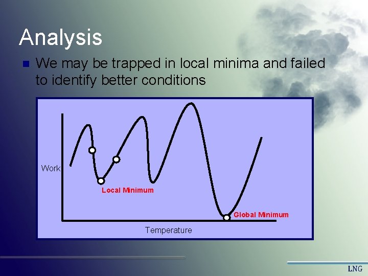
Analysis n We may be trapped in local minima and failed to identify better conditions Work Local Minimum Global Minimum Temperature
Conclusions n n We successfully simulated several LNG production plants We obtained capital and operating costs and determined a ranking Some connection with existing trends were identified, but other results do not coincide with market trends We discussed why discrepancies may arise.
Questions?
References n n n n "Overview: LNG Basics. " Center for Liquefied Natural Gas. 2008. Center for Liquefied Natural Gas. 3 Feb 2008. <http: //www. lngfacts. org/About-LNG/Overview. asp>. http: //www. globalsecurity. org/military/systems/ship/tanker-lng-history. htm www. fpweb. com/200/Issue/Article/False/67449/Issue Fossil Energy Office of Communications. U. S. Department of Energy: Fossil Energy. 18 Dec 2007. U. S. Department of Energy. 3 Feb 2008. . <http: //www. fossil. energy. gov/programs/oilgas/storage/index. html>. "Mustang receives U. S. patent for LNG liquefaction process. " Scandanavian Oil and Gas Magazine. 14 Dec 2007. 3 Feb 2008. <http: //www. scandoil. com/moxie-bm 2/news/mustangreceives-us-patent-for-lng-liquefaction-pr. shtml>. Spilsbury, Chris; Yu-Nan Liu; et al. "Evolution of Liquefaction Technology for today's LNG business. " Journees Scientifiques Et Techniques (2006) Process Selection is Critical to onshore LNG economics. ” World-Oil Magazine. February 2006 com <http: //www. worldoil. com/Magazine/MAGAZINE_DETAIL. asp? ART_ID=2808&MONTH_YEAR=F eb-2006> Flynn, Thomas N. “Cryogenic Engineering. ” Second edition. Marcel Dekker. New York- NY. 2005