ERDA for measurement of hydrogen in PV applications


- Slides: 15

ERDA, for measurement of hydrogen in PV applications -- DERF 06/08 -Presented by: Andrew Thomson Supervisor: Dr Keith Mc. Intosh

Introduction § Specialised form of ion beam analysis. § Understand the role of H in passivation. § Measuring SC dielectric coatings and silicon—dielectric interfaces, after various treatments. § Overview:

Really what is ERD – fancy RBS § Measurement of backscattered particle energy. § Gives energy count and yield. § Knowing “R crosssections” give quantative measurement.

Generalised ERD setup § Forward scatter measured. § Incident ion suppressed. § Experimental crosssections. § RBS and ERD combined. § Generally energy only is measured.

Resolution limits § Detection limits: • For an optimised sample 20 ppm, up to 1000 nm depth. § Comparative techniques: • SIMS, similar resolution, better depth resolution. • FTIR, measures bonds, unsure of resolution.

The physics of ERD – descriptively § Single atomic layer § Multiple layers add spread • Increased variance. • Straggle lowers energy. • Measured spectrum convolution of input spectrum with straggling function.

The physics of ERD – descriptively § Example of an ideal RBS spectrum: • Generalised two part dielectric on a substrate. § Example of an actual silicon substrate.

Setup at ANSTO – Lucas Heights

Setup at ANSTO – Lucas Heights § 3 Me. V tandem accelerator with a He ion source § So far we have used an incident power of 1. 8 Me. V. § Mylar foil § RBS: • Θ = 170 °, β = 60 °, α = 70 °. § ERD: • Θ = 30 °, β = 80 °, α = 70 °.

RBS and ERD measurements § RB Spectra of a Ti. O 2 dielectric layer on. § ERD specra § Shows surface absorption of H

Modelling Spectrums § Guess work: • • Layers. Energy per channel. Incident flux. Substrate. § Experience needed:

Modelling Spectrums – RBS Ti. O 2

Modelling Spectrums – ERD Ti. O 2

PECVD vs. Ti. O 2 § PECVD § Optimised Ti. O 2

Plans for PV applications of ERDA § Hydrogen characterisation: • • Basic PV processing steps. PV dielectrics. Hydrogenated Ti. O 2 Degradation processes. § Other applications: • Boron, and phos profiles. • Densification of Ti. O 2.
 Erda acres water
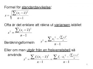
 Varians formel
 Datorkunskap för nybörjare
 Tack för att ni har lyssnat
 Vad står k.r.å.k.a.n för
 Läkarutlåtande för livränta
 Treserva lathund
 Tack för att ni lyssnade
 Påbyggnader för flakfordon
 Egg för emanuel
 Tobinskatten för och nackdelar
 Atmosfr
 Vad är vanlig celldelning
 Byggprocessen steg för steg
 Personlig tidbok
 Rutin för avvikelsehantering
