Engineering Classification Systems for Rocks INTACT ROCK MASS


 Classification of intact rock: •")
 /Modulus Ratio Three ratio intervals are employed for the")
 • Fissuration factor, C = 1/2 S(p x H+k x")

 • Competent Rock – excavation requires no added")
 (Deere et al. 1967) • Aim : to provide")
 and Indices • Quality and deformability = f (discontinuity) •")
")


 compressional (c) wave")

 • Rock")
 / Geomechanics Claasification • Rating Concept • Weightage • Total")
, Geocmechanics Classification (Bieniawski, 1976, 1989) • Classifies rock mass according")


, Barton et al. , 1974")
 = crude measure of")

 (1972) • Introduced the concept of rating components to")
 rock type origin (b)")
 joint")
 overall rock mass quality")

- Slides: 39
Engineering Classification Systems for Rocks INTACT ROCK MASS Rock mass refers to in situ rock with all its inherent geomechanical anisotropies
Engg classification • Geologists: have a genetic bias, provide little information relating to engg behaviour • Tests which are used for engg classification are called Index Test • If right index tests are chosen, then rocks having similar index properties, irrespective of their origin, will probably exhibit similar engg performance • First Major classification by Terzaghi (1946) • After that, there have been many classification = some are oversimplified, misapplied = led to chaos, multiplicity • Last two decades = some effort done, to bring some order from the chaos
Bases of Engg Classification Lithology Strength Modulus of deformation Discontinuities, Joint: spacing, inclination, orientation, roughness, groundwater flow • In situ stress • •
Terzaghi’s Classification • Terzaghi : first to attempt classification • Bases : discontinuity, weathering Term / Description Intact = neither joints nor hair cracks Stratified = individual strata with little or no resistance against separation Moderately Jointed = blocks between joints are intimately interlocked Blocky and Seamy = rocks consists of chemically unweathered rock fragments which are entirely separated from each other Crushed = chemically unweathered, like crusher run material Squeezing = slowly advances into tunnel Swelling = expansion due to swelling capacity
Disadvantage of Terzaghi’s Classification • Overlooked the properties of rocks • Granite, mudstone may belong to one group as per Terzaghi • But their mechanical properties differ significantly
Engineering classification of weathered rock Based on Weathering Grade Description Lithology Foundations VI Soil Some organic content, no original structure Unsuitable V Completely weathered Decomposed soil, some remnant structure Assess by soil testing IV Highly weathered Partly changed to soil, soil > rock Variable and unreliable III Moderately weathered Partly changes to soil, rock > soil Good for most small structures II Slightly weathered Increased fractures and mineral staining Good for anything except large dams I Fresh rock Clean rock Sound
Classification of Intact Rock • Deere and Miller (1966) Classification of intact rock: • Bases: unconfined (uniaxial) compressive strength ( 1) • Young’s Modulus (E) – Rocks are subdivided into five strength categories on a geometric progression basis based on unconfined (uniaxial) compressive strength ( 1) Description/ Class Very high A High B Medium C Low D very low E
Based on Young’s Modulus (E) /Modulus Ratio Three ratio intervals are employed for the modulus ratio; high(H) – medium(M) – low(L). Rocks are therefore classed as BH (high strength- high ratio); CM (medium strength – medium ratio), etc.
C-factor classification (Hansagi, 1974) • Fissuration factor, C = 1/2 S(p x H+k x n) • S = length of drill hole • p = number of cylindrical samples which can be obtained from cores corresponding to length S • H = height of the cylindrical samples used for compression testing • k = total length of core fragments with cylindrical heights > the core diameter • n = number of core samples
Coates Classification 1. Uniaxial com strength : Weak, Strong, Very strong 2. Pre-failure Deformation: Elastic, Viscous 3. Failure Characteristics: Brittle, Plastic 4. Gross Homogeneity: Massive, Layered 5. Continuity: Solid, Blocky, Broken
USBM Classification (US Bureau of Mines) • Competent Rock – excavation requires no added support • Massive-Elastic – homogeneous and isotropic • Bedded- elastic but laminated, little cohesion b/w beds • Massive-Plastic – Rocks that will have creep flow under low stress
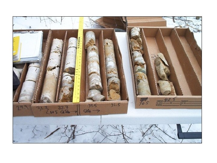
Rock Quality Designation Index (RQD) (Deere et al. 1967) • Aim : to provide a quantitative estimate of rock mass quality from drill logs • Equal to the percentage of intact core pieces longer than 100 mm in the total length of core
Rock Quality Designation (RQD) and Indices • Quality and deformability = f (discontinuity) • Core Recovery = total core recovered/length of drilling – Expressed in %, good core recovery = good quality rock – Poor core recovery = poor quality of rocks – In core recovery, all lengths of cores are counted • In RQD, only cores with >10 cm length are considered • Quantitative estimate of rock mass quality from drill core logs RQD = % intact core pieces >10 cm in total length of core Rock Quality Designation index, or RQD, was introduced by Don Deere in 1963. It judges rock quality based solely on measurements of recovered rock core
Rock Quality Designation (RQD)
Natural joint surface vs core broken during operation • Mechanical breaking of cores caused by drilling processes • Natural joint surface
Broken cores • Cores broken during handling or drilling = fresh irregular breaks = can be fitted • Natural Joint surface – broken surface smooth, pieces cannot be fitted • For RQD determination, International Society for Rock Mechanics recommends a core size of at least 54. 7 mm (NX) diameter drilled with double tube core barrels
RQD A. Very poor B. Poor C. Fair D. Good E. Excellent RQD% 0 – 25 25 – 50 50 – 75 75 – 90 90 - 100
RQD : when core is unavailable • RQD = 115 – 3. 3 Jv, for Jv between 4. 5 and 30. • For Jv < 4. 5, RQD is 100%, and for Jv > 30, RQD is 0%. Jv = number of joints per m 3 volume of rock mass
Outcrop Measurements of RQD
RQD • Directionally dependant parameter • Intended to indicate rock mass quality in-situ • Adapted for surface exposures as ‘Jv’ number of discontinuities per unit volume • Used as a component in the RMR and Q systems • Palmstrom (1982) • Priestai Hudsona (1976) l - number of joints per unit length
Mass factor = j • j = ratio of deformation modulus of rock mass (in situ, outcrop)/ that of intact rock core comprising the same lithology • j = reflects effects of discontinuities
Velocity ratio • Vcf/Vcl • Vcf = in situ (field f) compressional (c) wave velocity • Vcl = compressional (c) wave velocity in lab (l), intact rock core • Difference in Vcf and Vcl caused by structural discon
Quality RQD% classification / Rock Quality Description Very Poor 0 -25 Poor 25 -50 Mass Velocity Fracture C-factor Factor, j Ratio, frequenc Vcf/Vcl y <0. 2 0 -0. 2 -0. 4 >15 15 -8 Fair 50 -75 0. 2 -0. 5 0. 4 -0. 6 8 -5 Good 75 -90 0. 5 -0. 8 0. 6 -0. 8 5 -1 Excellent 90 -100 0. 8 -1. 0 <1 0 -0. 150. 300. 450. 65 -1. 0
Multi parameter Rock Mass Classification Schemes • Rock Mass Structure Rating (RSR) • Rock Mass Rating (RMR) • Rock Tunnelling Quality Index (Q) • Geological Strength Index (GSI)
Rock Mass Rating (RMR) / Geomechanics Claasification • Rating Concept • Weightage • Total Rating
Rock Mass Rating (RMR), Geocmechanics Classification (Bieniawski, 1976, 1989) • Classifies rock mass according to 6 rated parameters: – UCS (unconfined com strength) – RQD – Spacing of discontinuities – Condition of discontinuities – Groundwater conditions – Discontinuity orientation
RMR or ‘Geomechanics Classification’ RMR emphasizes STRUCTURAL consideration and Orientation
Rock Mass Rating System 1976 to 1989 Bieniawski • System refined by greater data • Ratings for parameters changed • Adapted by other workers for different situations • PROJECT SPECIFIC SYSTEMS
Development of Rock Mass Rating System
Rock Mass Rating System Rating Class Description 81 -100 I Very Good Rock 61 -80 II Good Rock 41 -60 III Fair Rock 12 -40 IV Poor Rock Less than 20 V Very Poor Rock
Rock Tunnelling Quality Index, Q (or Norwegian Q system), Barton et al. , 1974 RQD = Rock Quality Designation Jn = Joint set number Jr = Joint roughness factor Ja = Joint alteration and clay fillings Jw = Joint water inflow or pressure SRF = stress reduction factor Q Range 0. 001 to 1000 Exceptionally poor squeezing : 0. 001 Exceptionally good unjointed Rock : 1000 Good Bad 100 - 10 1 – 20 4 -1 1 – 20 1 – 0. 1 1 – 20
Q system Mistake in Bell New Volume/Indian Ed • (RQD/Jn) = crude measure of block size • (Jr/Ja) = roughness/friction of surfaces • (Jw/SRF) = ratio of two stress parameters (active stress) • Q Does NOT include joint orientation
Guideline properties of Rock Mass Classes
Rock Mass Structure Rating (RSR) (1972) • Introduced the concept of rating components to arrive at a numerical value • Demonstrates the logic in a quasi-quantitative rock mass classification • Has limitations as based on small tunnels supported by steel sets only RSR = A + B + C Maximum value of RSR = 100
Rock Structure Rating Parameter A: General area geology Considers (a) rock type origin (b) rock ‘hardness’ (c) geotechnical structure
Rock Structure Rating Parameter B: Geometry : Effect of discontinuity pattern Considers (a) joint spacing (b) joint orientation (strike and dip) (c) direction of tunnel drive
Rock Structure Rating Parameter C: Groundwater, joint condition Considers (a) overall rock mass quality (on the basis of A + B) (b) joint condition (c) water inflow
Using Rock Mass Classification Systems • RMR and Q most widely used • Both use similar parameters; difference in weighting • Q Does NOT include joint orientation • RMR emphasizes STRUCTURAL consideration and Orientation