ELEMENTS OF A TYPICAL CROSSSECTION OF ROAD AND


 materials. Its")


 is \"the black stuff\" used as")


 Design procedure Based on the performance of existing designs and using")
 Design traffic The method considers traffic in terms of the cumulative")
 Initial traffic is determined in terms of commercial vehicles per day")
 Vehicle Damage Factor Introduction to Transportation Engineering 28. 3 Tom V.")
 Pavement composition � Sub-base � Base � Sub-base materials comprise natural")
 Numerical example Design the pavement for construction of a new bypass")


 emergency use lateral")

- Slides: 57
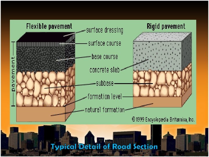
ELEMENTS OF A TYPICAL CROSS-SECTION OF ROAD AND HIGHWAY DRAINAGE
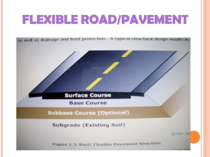
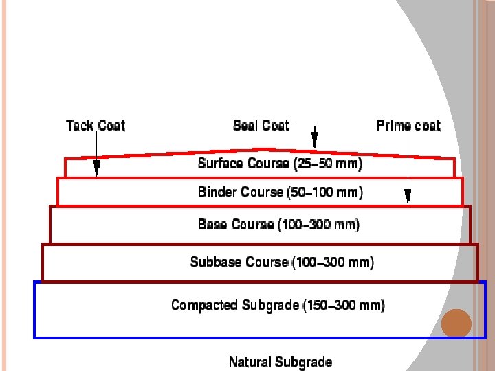
TYPICAL PAVEMENT LAYERS
I NTRODUCTION An open, generally public way for the passage of vehicles, people, and animals. WHAT ISROAD /PAVEMENT ? Roads have a life expectancy of between 20 - 30 years. Finish with a hard smooth surface (pavement) helped make them durable and able to withstand traffic and the environment. Road pavements deteriorate over time due to the impact of traffic, particularly heavy vehicles, and environmental factors. Purpose : Many rely on paved roads to move themselves and their products rapidly and reliably
Functions : One of the primary functions of a pavement is load distribution which can be characterized by the tire loads; tire configurations; repetition of loads; distribution of traffic across the pavement; and vehicle speed. Pavement material and geometric design can affect quick and efficient drainage thus eliminating moisture problems such as mud and ponding (puddles). Consist of: i)Surface drainage : Removing all water present on the pavement surface, sloping, chambers, and kerbs. ii)Subsurface drainage : Removing water that seep into or is contained in the underlying sub-grade.
Several elements make up the roadway. Each layer. T YPICAL represents one of the elements of the pavement system. All these elements work together to provide a quality durable pavement. C OMPONENTS
SUB-GRADE BASE EMBANKMENT TYPICAL COMPONENTS SUB-DRAIN PAVEMENT
Embankment When roads are built higher surrounding ground, a compacted earth embankment is built. than structure of called an the The embankment is built to support the other three layers of the pavement system. The construction of embankments for roadways can take up a large part of the total cost. Embankments can be made from almost any common type of deposit except topsoil.
Sub-grade The sub-grade is made of soils that have been specially prepared to meet the requirements to support the other two layers. The sub-grade is a selected soil material that compacted is carefully to provide uniform support to the pavement. The sub-grade lies directly on either the embankment or the native soil.
Base The base is a mixture of crushed rock. The base layer provides uniform support to the pavement and allows water that penetrates any joints or cracks in the pavement to move quickly to the sub- drain without saturating and softening the sub-grade. The base layer lies directly on top of the sub-grade and is built of clean sand or rock.
Pavement The top layer is the pavement. The pavement materials can either be Hot Mix Asphalt (HMA) and Portland Cement Concrete (PCC). The pavement itself resists bending, and distributes vehicle weights over a large area.
Sub-Drain The sub-drain collects water from the base and the sub-grade and drains that water into the ditch. The sub-drain sits alongside the pavement, base and sub-grade. The sub-drain is basically a trench with a perforated pipe near the bottom, surrounded by clean coarse-size rock which allows rapid transportation of water.
SUBDRAIN
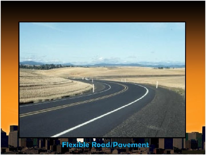
Flexible pavements are those which are surfaced with bituminous (or asphalt) materials. Its "flexible" since the total pavement structure "bends" or "deflects" due to traffic loads. Generally this type of pavement requires some sort of maintenance or rehabilitation every 10 to 15 years.
Each layer receives the loads from the above layer, spreads them out, and then passes on these loads to the next layer below.
Material layers are usually arranged in order of descending load bearing capacity with the highest load bearing capacity material (and most expensive) on the top and the lowest load bearing capacity material (and least expensive) on the bottom
Thus, the further down in the pavement structure a particular layer is, the less load (in terms of force per area) it must carry
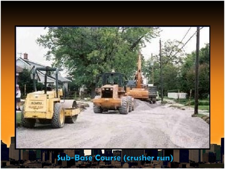
3. 1 S UB -BA SE C OUR SE This is the layer (or layers) under the base layer. A sub-base is not always needed. A proper sub-base consists of various sizes of crushed stone aggregate, commonly known as crusher run. Depending on the sub soils on your site you may need 8 -12 inches of various sizes of sub-base. With well drained sub soils, without movement, added sub-base materials may be sufficient, along with proper pitch & grade. If the sub-base is knowingly sufficient, grading & compaction with vibratory roller or plate compactor in small areas, may be all that is necessary.
3. 1 SUB-BASE COURSE It functions primarily as structural support but it can also help: a)Minimize the intrusion of fines from the sub-grade into the pavement structure. b)Improve drainage. c)Minimize frost action damage. d)Provide a working platform for construction. The subbase generally consists of lower quality materials than the base course but better than the sub-grade soils.
3. 2 BASE COURSE The first coat to be placed, on top of your proper subbase, is the base course. provides additional It load distribution and contributes to drainage and frost resistance. The base is built of clean sand or rock. The base layer providesuniform support to the pavement and allows water that penetrates any joints or cracks in the pavement to move quickly to the sub -drain without saturating and softening the sub-grade. This coat is put in place for strength, plus it works as a true-leveler course, to take out any small imperfections in the grade.
3. 2 BASE COURSE After the binder is put into place with paver, it is compacted with a vibratory roller for tighter density and added strength. Base courses are usually constructed out of: i)Aggregate: Base courses are most typically constructed from durable aggregates that will not be damaged by moisture or frost action such as dense bitumin macadam (dbm) ii)HMA: In certain situations where high base stiffness is desired, base courses can be constructed using a variety of HMA mixes.
3. 3 SURFACE COURSE This is the top layer which comes in contact with traffic. It normally contains the highest quality materials. It serves to prevent the entrance of excessive quantities of surface water into the underlying base & sub-grade. It is sometimes subdivided into two layers: i)Wearing Course: A layer in direct contact with traffic loads. It is meant to take the impact of traffic wear and can be removed and replaced as it becomes worn. ii)Intermediate/Binder Course: This layer provides the bulk of the HMA structure. It's main purpose is to distribute load. It may compose of one or several HMA sublayers.
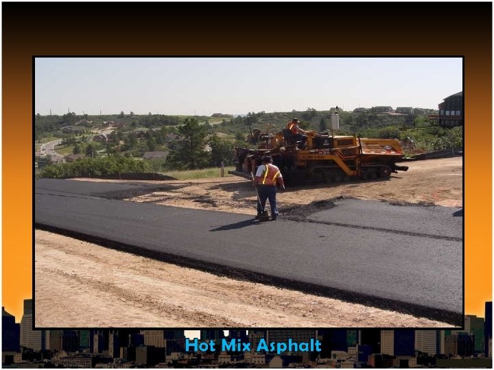
3. 3 SURFACE COURSE Hot mix asphalt (HMA) is "the black stuff" used as a pavement material. Its a combination of aggregate and asphalt binder mixed together at elevated temperatures that forms a hard, strong construction material when cooled to suitable temperatures. Also known as "asphalt concrete" (AC or ACP), "asphalt", "blacktop" or "bitumin“ They must be mixed very well to make sure that the rocks are evenly distributed in the mix. Each rock piece must be completely coated by the asphalt.
3. 3 SURFACE COURSE Once it is well mixed, it is laid down on the roadway as pavement. The pavement must then be compacted to achieve uniform density. If this is not done properly, it can reduce the lifetime of the pavement and increase the costs of maintaining the road. It usually costs less. The life expectancy of an asphalt pavement is between 15 to 20 years.
ADVANTAGES OF FLEXIBLE PAVEMENT v Adjusts to limited differential settlement v Easily, quickly constructed and repaired v Additional thickness can be added v Quieter smoother (Generally)
DISADVANTAGES OF FLEXIBLE PAVEMENT Properties may change over time as pavement ages Generally shorter service life before first rehabilitation May experiences moisture problems
PAVEMENT DESIGN (FLEXIBLE) Design procedure Based on the performance of existing designs and using analytical approach, simple design charts and a catalogue of pavement designs are added in the IRC code. The pavement designs are given for subgrade CBR values ranging from 2% to 10% and design traffic ranging from 1 msa to 150 msa for an average annual pavement temperature of 35 C. Using the following simple input parameters, appropriate designs could be chosen for the given traffic and soil strength: Design traffic in terms of cumulative number of standard axles; and v CBR value of subgrade. v
PAVEMENT DESIGN (FLEXIBLE) Design traffic The method considers traffic in terms of the cumulative number of standard axles (8 Tons) to be carried by the pavement during the design life. This requires the following information: Initial traffic in terms of CVPD (Commercial Vehicle per day) v Traffic growth rate during the design life v Design life in number of years v Vehicle damage factor (VDF) v Distribution of commercial traffic over the carriage way. v
PAVEMENT DESIGN (FLEXIBLE) Initial traffic is determined in terms of commercial vehicles per day (CVPD). For the structural design of the pavement only commercial vehicles are considered assuming laden weight of three tonnes or more and their axle loading will be considered. Estimate of the initial daily average traffic flow for any road should normally be based on 7 -day 24 -hour classified traffic counts (ADT). In case of new roads, traffic estimates can be made on the basis of potential land use and traffic on existing routes in the area. Traffic growth rates can be estimated (i) by studying the past trends of traffic growth, and (ii) by establishing econometric models. If adequate data is not available, it is recommended that an average annual growth rate of 7. 5 percent may be adopted. Design life For the purpose of the pavement design, the design life is defined in terms of the cumulative number of standard axles that can be carried before strengthening of the pavement is necessary. It is recommended that pavements for arterial roads like PNH, SNH should be designed for a life of 15 years and other categories of roads for 10 years.
PAVEMENT DESIGN (FLEXIBLE) Vehicle Damage Factor Introduction to Transportation Engineering 28. 3 Tom V. Mathew and K V Krishna Rao CHAPTER 28. IRC METHOD OF DESIGN OF FLEXIBLE PAVEMENTS NPTEL May 3, 2007 The vehicle damage factor (VDF) is a multiplier for converting the number of commercial vehicles of different axle loads and axle configurations to the number of standard axle-load repetitions. It is defined as equivalent number of standard axles per commercial vehicle. The VDF varies with the axle configuration, axle loading, terrain, type of road, and from region to region. The axle load equivalency factors are used to convert different axle load repetitions into equivalent standard axle load repetitions. For these equivalency factors refer IRC: 37 2001. The exact VDF values are arrived after extensive field surveys. Vehicle distribution A realistic assessment of distribution of commercial traffic by direction and by lane is necessary as it directly affects the total equivalent standard axle load application used in the design. Until reliable data is available, the following distribution may be assumed. ü Single lane roads: Traffic tends to be more channelized on single roads than two lane roads and to allow for this concentration of wheel load repetitions, the design should be based on total number of commercial vehicles in both directions. ü Two-lane single carriageway roads: The design should be based on 75 % of the commercial vehicles in both directions.
PAVEMENT DESIGN (FLEXIBLE) Pavement composition � Sub-base � Base � Sub-base materials comprise natural sand, gravel, laterite, brick metal, crushed stone or combinations thereof meeting the prescribed grading and physical requirements. The sub-base material should have a minimum CBR of 20 % and 30 % for traffic upto 2 msa and traffic exceeding 2 msa respectively. Sub-base usually consist of granular or WBM and the thickness should not be less than 150 mm for design traffic less than 10 msa and 200 mm for design traffic of 1: 0 msa and above. The recommended designs are for unbounded granular bases which comprise conventional water bound macadam Introduction to Transportation Engineering 28. 4 Tom V. Mathew and K V Krishna Rao CHAPTER 28. IRC METHOD OF DESIGN OF FLEXIBLE PAVEMENTS NPTEL May 3, 2007 (WBM) or wet mix macadam (WMM) or equivalent confirming to MOST specifications. The materials should be of good quality with minimum thickness of 225 mm for traffic up to 2 msa an 150 mm for traffic exceeding 2 msa. Bituminous surfacing The surfacing consists of a wearing course or a binder course plus wearing course. The most commonly used wearing courses are surface dressing, open graded premix carpet, mix seal surfacing, semi-dense bituminous concrete and bituminous concrete. For binder course, MOST specifies, it is desirable to use bituminous macadam (BM) for traffic upto o 5 msa and dense bituminous macadam (DBM) for traffic more than 5 msa.
PAVEMENT DESIGN (FLEXIBLE) Numerical example Design the pavement for construction of a new bypass with the following data: Two lane carriage way Initial traffic in the year of completion of construction = 400 CVPD (sum of both directions) Traffic growth rate = 7. 5 % Design life = 15 years Vehicle damage factor based on axle load survey = 2. 5 standard axle per commercial vehicle Design CBR of subgrade soil = 4%. Solution Distribution factor = 0. 75 � = 7200000 = 7. 2 msa Total pavement thickness for CBR 4% and traffic 7. 2 msa from our Chart = 525 mm + 200 mm SR Pavement composition can be obtained by interpolation from Pavement Thickness chart. (a) Bituminous surfacing = 40 mm AC + 60 mm DBM (b) Base course = 200 mm WWM (c) sub-base = 225 mm GSB (d) Soil replacement of 200 mm
PAVEMENT PURPOSE � Carries traffic smoothly and safely with minimum cost. � Distribute the applied vehicle loads to the sub-grade. � Acceptable riding quality, adequate skid resistance, favorable light reflecting characteristics, and low noise pollution.
DESIGN PROCEDURE DESIGN TRAFFIC: Initial traffic Traffic growth rate Design life Vehicle damage factor (VDF) Vehicle distribution.
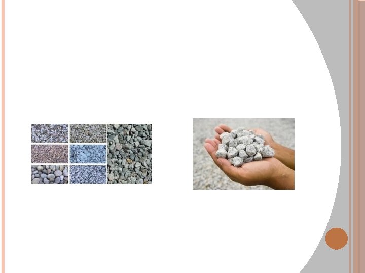
TESTING OF AGGREGATES Desirable properties of aggregates: Strength Hardness Toughness Shape of aggregates Adhesion with bitumen Durability Freedom from deleterious particles
AGGREGATE TESTS � � � � Crushing test Abrasion test Impact test Soundness test Shape test Specific gravity and water absorption test Bitumen adhesion test
BITUMEN Different forms of Bitumen Cutback bitumen Bitumen emulsion Bituminous primers Modified bitumen
CUTBACK BITUMEN: Solvent used lowers the viscosity of bitumen. The solvent from the bituminous material will evaporate and the bitumen will bind the aggregate. The distillates used areene, dieselkeros oil, and naphtha, furnace oil.
Bitumen emulsion: This type of bitumen is a liquid with aqueous medium containing 50 to 60% bitumen in a finely divided form. It is used for making and repairing roads
� BITUMINOUS PRIMERS : THE DISTILLATE IS ABSORBED BY THE ROAD SURFACE ON WHICH IT IS SPREAD These are prepared in road sites by mixing penetration bitumen with petroleum distillate
MODIFIED BITUMEN: CERTAIN ADDITIVES OR BLEND OF ADDITIVES CALLED AS BITUMEN MODIFIERS CAN IMPROVE � PROPERTIES OF BITUMEN AND BITUMINOUS MIXES. Bitumen treated with these modifiers is known as modified bitumen �
Roads CONSTRUCTION PROCEDURE OF BT � � The existing surface is prepared by removing the pot holes or rust if any. The irregularities are filled in with premix chippings at least a week before laying surface course. The premix is prepared in a hot mix plant of a required capacity with the desired quality control. The hot mixed material is collected from the mixture by the transporters, carried to the location, A mix after it is placed on the base course is thoroughly compacted by rolling at a speed not more than 5 km per hour. The initial or break down rolling is done by 8 to 12 tonnes roller and the intermediate rolling is done with a fixed wheel pneumatic roller of 15 to 30 tonnes having a tyre pressure of 7 kg per sq. cm. the wheels of the roller are kept damp with water.
� � THE FINAL ROLLING OR FINISHING IS DONE BY 8 TO 10 TONNES TANDOM ROLLER. Periodical checks are made for , Aggregate grading b) Grade of Bitumen c) Temperature of aggregate d) Temperature of paving mix during mixing and compaction a)
GEOMETRIC STANDARDS OF BT ROADS � The carriageway or the black top portion of the road is not really flat. There is a transfer slope which is provided and that transfer slope is known as camber.
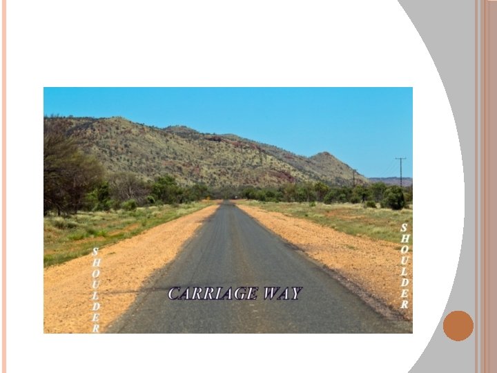
� BASICALLY THE TRAVELED WAY WHICH IS USED FOR MOVEMENT OF VEHICLES, IT TAKES THE VEHICULAR LOADING AND PREDOMINANT VEHICLE LOADS IS SHARED BY THIS COMPONENT WHICH IS CALLED ‘CARRIAGEWAY’.
� THE BLACK TOP OF SURFACE AND ON EACH SIDE SOME EXTRA WIDTH OR EXTRA PORTION OF THE ROAD CALLED AS ‘SHOULDER’ � Basically it gives support to carriageway and provides a space for stop vehicle in case there is a necessity for a vehicle to stop. � If there is no shoulder then it will stop right on the carriageway and it will block the entire carriageway. � So, a shoulder is kept on each side of the carriage way which can be used by vehicle for stopping the vehicle and for parking. � So it is basically one half the difference between the road way width and the carriageway width. � The carriageway including separator or median, in case it is a divided road plus shoulders on both sides together is known as roadway width.
SELECTION OF APPROPRIATE CROSSSECTION ELEMENTS In selecting the appropriate cross-section elements and dimensions, designers need to consider a number of factors: Volume and composition (percent trucks, buses, and recreational vehicles) of the vehicular traffic expected to use the facility The likelihood that cyclists and pedestrians will use the route Climatic conditions
SHOULDERS Shoulders are the strips provided on both sides of the carriage way.
FUNCTIONS OF SHOULDERS accommodation of stopped vehicles (disabled vehicles, bus stops) emergency use lateral support for the pavement space for roadside facilities space for bicycles and pedestrians driving comfort (freedom from strain) improvement in sight distance improvement in capacity
WIDTH OF SHOULDERS Low-type roads -- minimum 0. 6 m, recommended 1. 8 -2. 4 m Shoulder provided for bicycles -- minimum 1. 2 m wide High-type roads -- minimum 3. 0 m, recommended 3. 6 m Shoulders should be continuous. Shoulders on bridges should have the same width as on the approach sections.