
Automotive Technology Principles Sixth Edition Diagnosis and Service

- Slides: 48
Automotive Technology Principles, Sixth Edition Diagnosis, and Service Chapter 99 Hydraulic Valves and Switches Copyright © 2018, 2015, 2011 Pearson Education, Inc. All Rights Reserved Copyright © 2020, 2016, 2012 Pearson Education, Inc. All Rights Reserved
LEARNING OBJECTIVES (1 of 2) 99. 1 Describe the operation of a pressuredifferential switch and a brake fluid level sensor switch. 99. 2 Describe the operation of the proportioning valve. 99. 3 Discuss the need and use of a metering valve. Copyright © 2020, 2016, 2012 Pearson Education, Inc. All Rights Reserved
LEARNING OBJECTIVES (2 of 2) 99. 4 List the components included in a combination valve. 99. 5 Describe how a brake light switch works. 99. 6 This chapter will help you prepare for the Brakes (A 5) ASE certification test content area “A” (Hydraulic, Power Assist, and Parking Brake Systems Diagnosis and Repair) Copyright © 2020, 2016, 2012 Pearson Education, Inc. All Rights Reserved
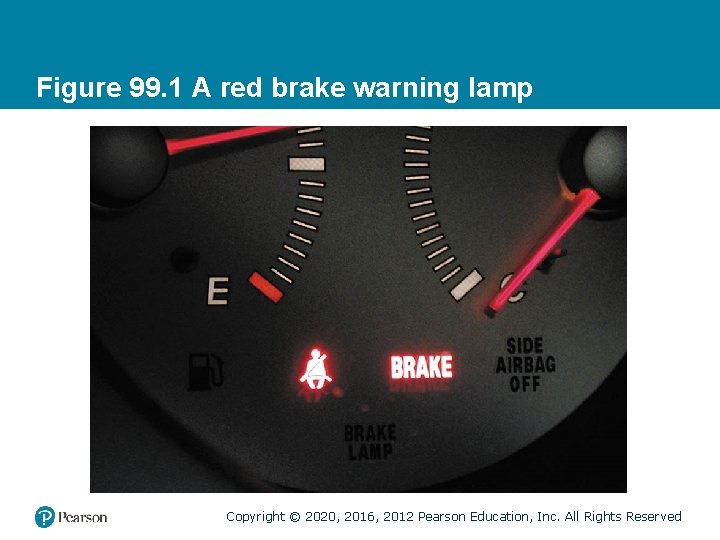
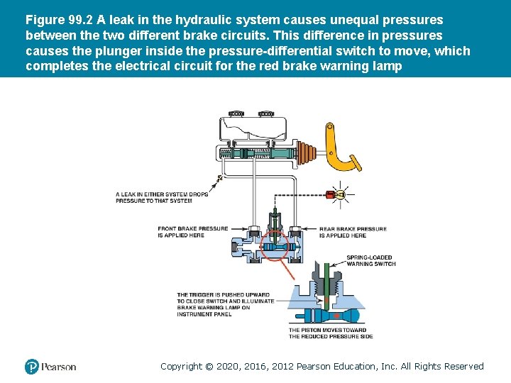
PRESSURE-DIFFERENTIAL SWITCH (BRAKE WARNING SWITCH) • Purpose and Function – Used with front/rear master split cylinders to warn the driver of a loss of pressure in one of the two separate systems by lighting the dashboard red brake warning indicator lamp. • Pressure-Differential Switch Reset – After the hydraulic system has been repaired and bled, moderate pressure on the brake pedal centers the piston in the switch and turns off the warning lamp. Copyright © 2020, 2016, 2012 Pearson Education, Inc. All Rights Reserved
Figure 99. 1 A red brake warning lamp Copyright © 2020, 2016, 2012 Pearson Education, Inc. All Rights Reserved
Figure 99. 2 A leak in the hydraulic system causes unequal pressures between the two different brake circuits. This difference in pressures causes the plunger inside the pressure-differential switch to move, which completes the electrical circuit for the red brake warning lamp Copyright © 2020, 2016, 2012 Pearson Education, Inc. All Rights Reserved
QUESTION 1: ? What is the purpose of the pressuredifferential switch? Copyright © 2020, 2016, 2012 Pearson Education, Inc. All Rights Reserved
ANSWER 1: To warn the driver of a loss of hydraulic pressure. Copyright © 2020, 2016, 2012 Pearson Education, Inc. All Rights Reserved
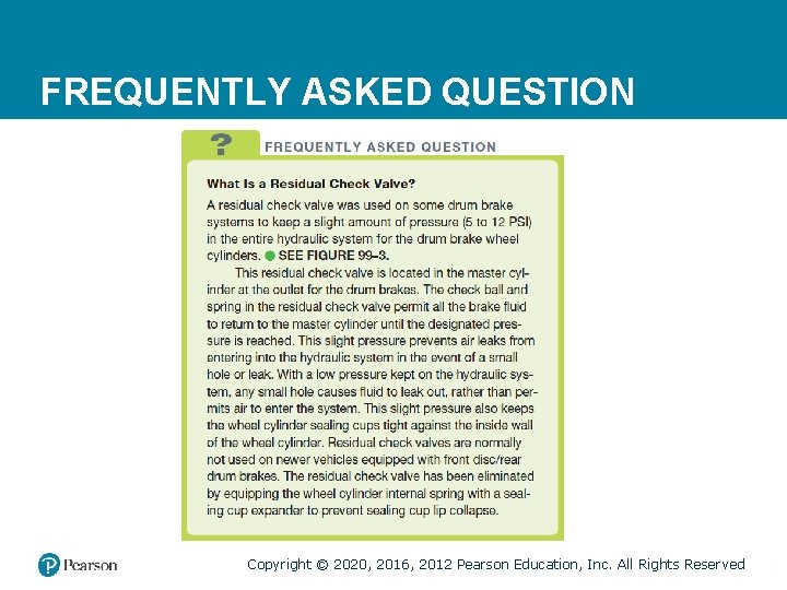
FREQUENTLY ASKED QUESTION Copyright © 2020, 2016, 2012 Pearson Education, Inc. All Rights Reserved
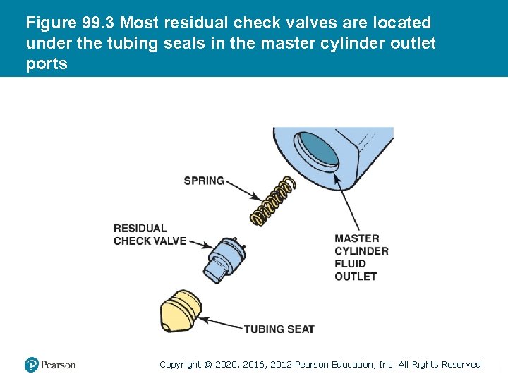
Figure 99. 3 Most residual check valves are located under the tubing seals in the master cylinder outlet ports Copyright © 2020, 2016, 2012 Pearson Education, Inc. All Rights Reserved
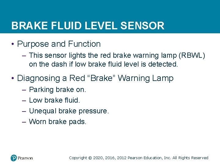
BRAKE FLUID LEVEL SENSOR • Purpose and Function – This sensor lights the red brake warning lamp (RBWL) on the dash if low brake fluid level is detected. • Diagnosing a Red “Brake” Warning Lamp – – Parking brake on. Low brake fluid. Unequal brake pressure. Worn brake pads. Copyright © 2020, 2016, 2012 Pearson Education, Inc. All Rights Reserved
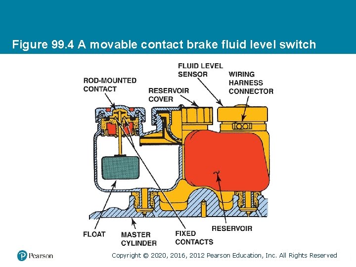
Figure 99. 4 A movable contact brake fluid level switch Copyright © 2020, 2016, 2012 Pearson Education, Inc. All Rights Reserved
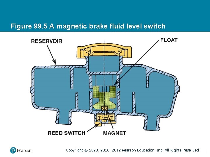
Figure 99. 5 A magnetic brake fluid level switch Copyright © 2020, 2016, 2012 Pearson Education, Inc. All Rights Reserved
TECH TIP Copyright © 2020, 2016, 2012 Pearson Education, Inc. All Rights Reserved
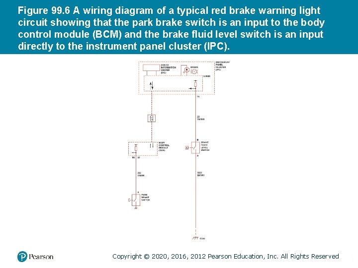
Figure 99. 6 A wiring diagram of a typical red brake warning light circuit showing that the park brake switch is an input to the body control module (BCM) and the brake fluid level switch is an input directly to the instrument panel cluster (IPC). Copyright © 2020, 2016, 2012 Pearson Education, Inc. All Rights Reserved
QUESTION 2: ? What reasons could cause the red brake warning lamp to come on during driving? Copyright © 2020, 2016, 2012 Pearson Education, Inc. All Rights Reserved
ANSWER 2: Parking brake on, Low brake fluid, Unequal brake pressure, Worn brake pads. Copyright © 2020, 2016, 2012 Pearson Education, Inc. All Rights Reserved
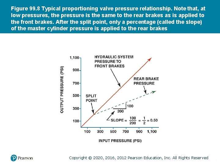
PROPORTIONING VALVE (1 OF 2) • Purpose and Function – A proportioning valve improves brake balance during hard stops by limiting hydraulic pressure to the rear brakes. • Proportioning Valve Operation – Before proportioning action begins, brake system hydraulic pressure must reach a minimum level, called the split point. – Above the split point, the proportioning valve allows only a portion of the pressure through to the rear brakes. Copyright © 2020, 2016, 2012 Pearson Education, Inc. All Rights Reserved
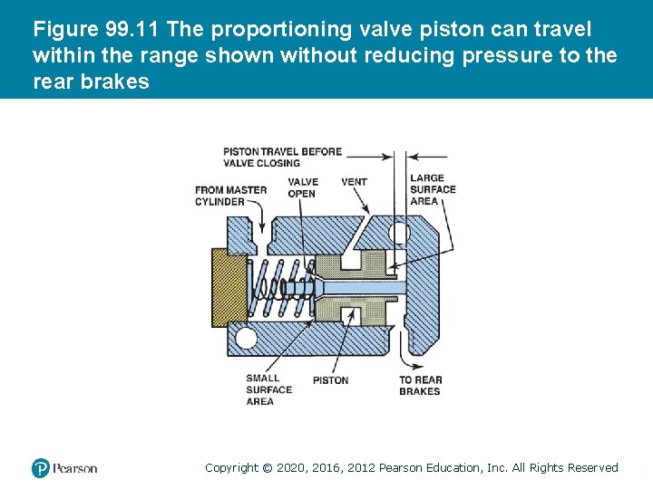
PROPORTIONING VALVE (2 OF 2) • Proportioning Valve Parts – A simple proportioning valve consists of a springloaded piston that slides in a stepped bore. • Height-Sensing Proportioning Valve – Varies the amount of pressure that can be sent to the rear brakes, depending on the height of the rear suspension. • Proportioning Valve Adjustment – Height-sensing proportioning valves should be adjusted when replaced. Consult service information. Copyright © 2020, 2016, 2012 Pearson Education, Inc. All Rights Reserved
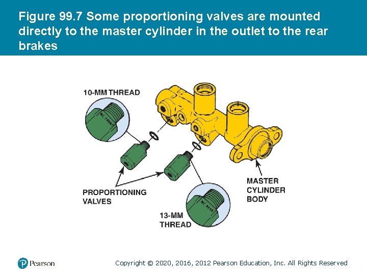
Figure 99. 7 Some proportioning valves are mounted directly to the master cylinder in the outlet to the rear brakes Copyright © 2020, 2016, 2012 Pearson Education, Inc. All Rights Reserved
Figure 99. 8 Typical proportioning valve pressure relationship. Note that, at low pressures, the pressure is the same to the rear brakes as is applied to the front brakes. After the split point, only a percentage (called the slope) of the master cylinder pressure is applied to the rear brakes Copyright © 2020, 2016, 2012 Pearson Education, Inc. All Rights Reserved
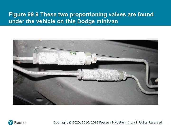
Figure 99. 9 These two proportioning valves are found under the vehicle on this Dodge minivan Copyright © 2020, 2016, 2012 Pearson Education, Inc. All Rights Reserved
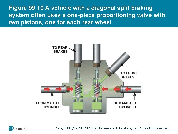
Figure 99. 10 A vehicle with a diagonal split braking system often uses a one-piece proportioning valve with two pistons, one for each rear wheel Copyright © 2020, 2016, 2012 Pearson Education, Inc. All Rights Reserved
Figure 99. 11 The proportioning valve piston can travel within the range shown without reducing pressure to the rear brakes Copyright © 2020, 2016, 2012 Pearson Education, Inc. All Rights Reserved
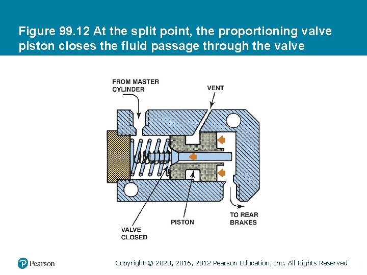
Figure 99. 12 At the split point, the proportioning valve piston closes the fluid passage through the valve Copyright © 2020, 2016, 2012 Pearson Education, Inc. All Rights Reserved
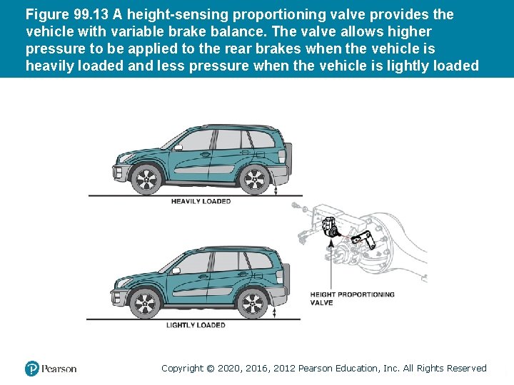
Figure 99. 13 A height-sensing proportioning valve provides the vehicle with variable brake balance. The valve allows higher pressure to be applied to the rear brakes when the vehicle is heavily loaded and less pressure when the vehicle is lightly loaded Copyright © 2020, 2016, 2012 Pearson Education, Inc. All Rights Reserved
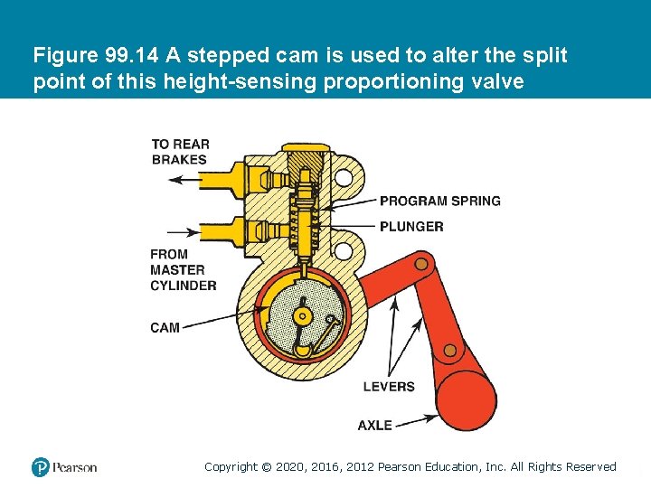
Figure 99. 14 A stepped cam is used to alter the split point of this height-sensing proportioning valve Copyright © 2020, 2016, 2012 Pearson Education, Inc. All Rights Reserved
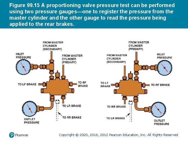
Figure 99. 15 A proportioning valve pressure test can be performed using two pressure gauges—one to register the pressure from the master cylinder and the other gauge to read the pressure being applied to the rear brakes. Copyright © 2020, 2016, 2012 Pearson Education, Inc. All Rights Reserved
ELECTRONIC BRAKE PROPORTIONING • Purpose and Function – Brake proportioning becomes a function of the antilock brake system. – Referred to as dynamic rear proportioning (DRP) • Parts and Operation – The controller energizes the inlet valve solenoids for both rear brakes to hold pressure in the lines and then energizes both rear outlet valve solenoids to release pressure, as needed. Copyright © 2020, 2016, 2012 Pearson Education, Inc. All Rights Reserved
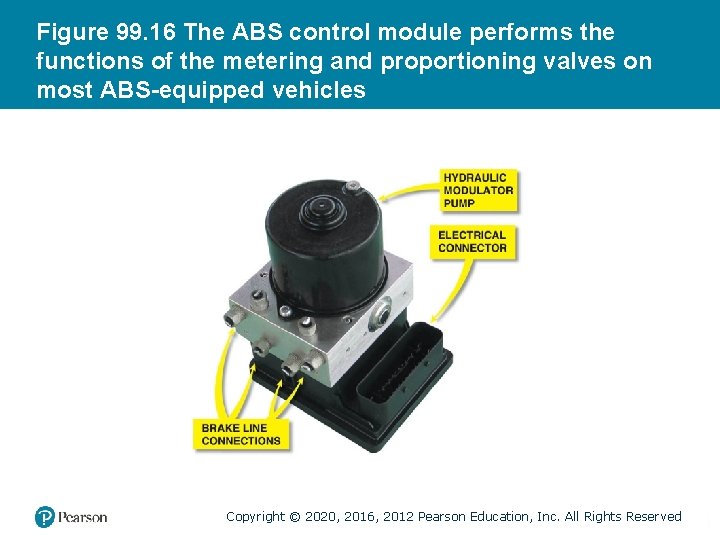
Figure 99. 16 The ABS control module performs the functions of the metering and proportioning valves on most ABS-equipped vehicles Copyright © 2020, 2016, 2012 Pearson Education, Inc. All Rights Reserved
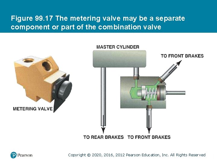
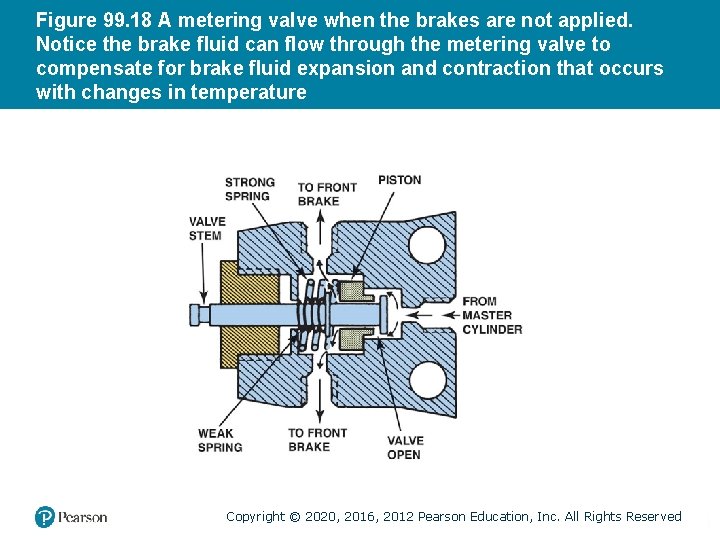
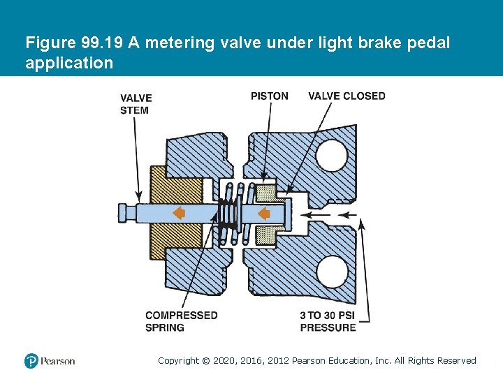
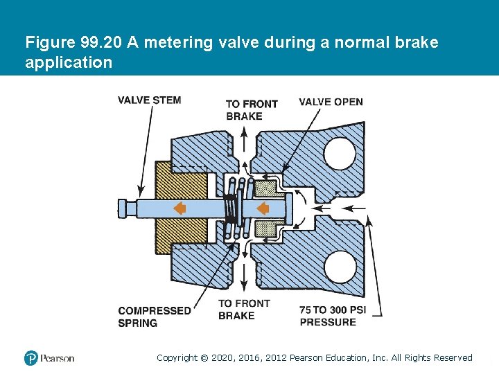
METERING VALVE (HOLD-OFF) OPERATION (1 OF 2) • Purpose and Function – The metering valve prevents the full operation of (holds off) the disc brakes until between 75 to 125 PSI is sent to the rear drum brakes to overcome rear-brake return spring pressure. • Parts and Operation – A metering valve consists of a piston controlled by a strong spring and a valve stem controlled by a weak spring. Copyright © 2020, 2016, 2012 Pearson Education, Inc. All Rights Reserved
METERING VALVE (HOLD-OFF) OPERATION (2 OF 2) • Systems Without Metering Valves – Braking systems that are diagonal split, such as those found on most front-wheel drive vehicles, do not use a metering valve. • Metering Valve Diagnosis and Testing – A defective metering valve can leak brake fluid and/or cause the front brakes to apply before the rear brakes. – Accurate testing of the metering valve can be accomplished using pressure gauges. Copyright © 2020, 2016, 2012 Pearson Education, Inc. All Rights Reserved
Figure 99. 17 The metering valve may be a separate component or part of the combination valve Copyright © 2020, 2016, 2012 Pearson Education, Inc. All Rights Reserved
Figure 99. 18 A metering valve when the brakes are not applied. Notice the brake fluid can flow through the metering valve to compensate for brake fluid expansion and contraction that occurs with changes in temperature Copyright © 2020, 2016, 2012 Pearson Education, Inc. All Rights Reserved
Figure 99. 19 A metering valve under light brake pedal application Copyright © 2020, 2016, 2012 Pearson Education, Inc. All Rights Reserved
Figure 99. 20 A metering valve during a normal brake application Copyright © 2020, 2016, 2012 Pearson Education, Inc. All Rights Reserved
COMBINATION VALVES • Most vehicle manufacturers combine the function of a proportioning valve with one or more other valves into one unit, called a combination valve. • Functions include: – Metering valve – Proportioning valve – Pressure-differential switch Copyright © 2020, 2016, 2012 Pearson Education, Inc. All Rights Reserved
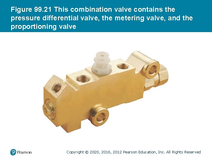
Figure 99. 21 This combination valve contains the pressure differential valve, the metering valve, and the proportioning valve Copyright © 2020, 2016, 2012 Pearson Education, Inc. All Rights Reserved
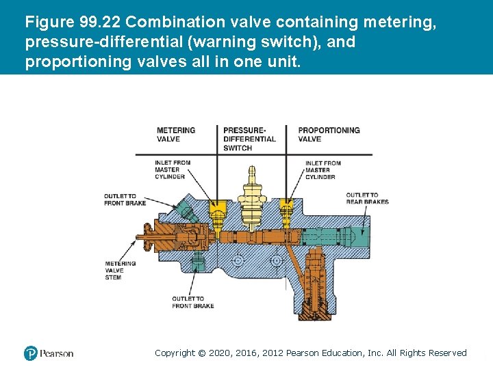
Figure 99. 22 Combination valve containing metering, pressure-differential (warning switch), and proportioning valves all in one unit. Copyright © 2020, 2016, 2012 Pearson Education, Inc. All Rights Reserved
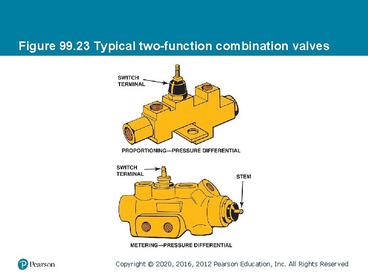
Figure 99. 23 Typical two-function combination valves Copyright © 2020, 2016, 2012 Pearson Education, Inc. All Rights Reserved
BRAKE PEDAL POSITION SENSOR/SWITCH (1 OF 2) • Purpose and Function – The brake pedal position (BPP) sensor or switch as an input to the body computer for many functions, including the following: – Brake lights – ABS input signal – Traction control is disabled when the brake pedal is depressed – Electronic stability control (ESC) system input signal Copyright © 2020, 2016, 2012 Pearson Education, Inc. All Rights Reserved
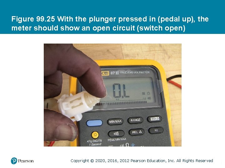
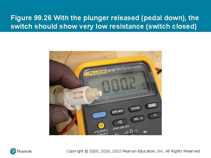
BRAKE PEDAL POSITION SENSOR/SWITCH (2 OF 2) • Brake Light Switch Testing – The brake light switch or sensor is most easily checked with the use of a scan tool. – A DMM (digital multimeter) set to Ohms can be used to check a brake switch on or off the vehicle. Copyright © 2020, 2016, 2012 Pearson Education, Inc. All Rights Reserved
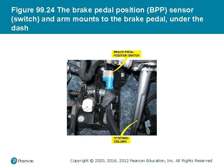
Figure 99. 24 The brake pedal position (BPP) sensor (switch) and arm mounts to the brake pedal, under the dash Copyright © 2020, 2016, 2012 Pearson Education, Inc. All Rights Reserved
Figure 99. 25 With the plunger pressed in (pedal up), the meter should show an open circuit (switch open) Copyright © 2020, 2016, 2012 Pearson Education, Inc. All Rights Reserved
Figure 99. 26 With the plunger released (pedal down), the switch should show very low resistance (switch closed) Copyright © 2020, 2016, 2012 Pearson Education, Inc. All Rights Reserved
QUESTION 3: ? What is the purpose of the brake pedal position sensor/switch? Copyright © 2020, 2016, 2012 Pearson Education, Inc. All Rights Reserved
ANSWER 3: An input to the following systems: Brake lights. ABS input signal. Traction control is disabled when the brake pedal is depressed. Electronic stability control (ESC) system input signal. Copyright © 2020, 2016, 2012 Pearson Education, Inc. All Rights Reserved
Copyright © 2020, 2016, 2012 Pearson Education, Inc. All Rights Reserved