Electricity and magnetism Chapter Five Capacitors and Dielectrics


- Slides: 26

Electricity and magnetism Chapter Five: Capacitors and Dielectrics nine weeks ﺳﻤﺮ ﺍﻟﺴﻠﻤﻲ / ﺃ

Chapter Five: Capacitors and Dielectrics One goal of physics is to provide the basic science for practical devices designed by engineers. The focus of this chapter is on one extremely common example, the capacitor, a device in which electrical energy can be stored as well as charge. The physics of capacitors can be generalized to other devices and to any situation involving electric fields. The first step in our discussion of capacitors is to determine how much charge can be stored. This “how much” is called capacitance.

1) Capacitance : Figure a shows some of the many sizes and shapes of capacitors. Figure b shows the basic elements of any capacitor: two isolated conductors of any shape. No matter what their geometry, flat or not, we call these conductors plates. Figure c shows a less general but more conventional arrangement, called a parallel-plate capacitor, consisting of two parallel conducting plates of area A separated by a distance d. The symbol we use to represent a capacitor ( ┤├) is based on the structure of a parallel-plate capacitor but is used for capacitors of all geometries. We assume for the time being that no material medium (such as glass or plastic) is present in the region between the plates. a b c d

1) Capacitance : When a capacitor is charged, its plates have charges of equal magnitudes but opposite signs: +q and -q. However, we refer to the charge of a capacitor q, and the potential difference V for a capacitor are proportional to each other; that is, ……(1) The proportionality constant C is called the capacitance of the capacitor. Its value depends only on the geometry of the plates and not on their charge or potential difference. The capacitance is a measure of how much charge must be put on the plates to produce a certain potential difference between them: The greater the capacitance, the more charge is required. The SI unit of capacitance that follows from Eq. 1 is the coulomb per volt. This unit occurs so often that it is given a special name, the farad (F):

1) Capacitance : Sample Problem 1 A storage capacitor on a random access memory (RAM) chip has a capacitance of 55 f. F. If it is charged to 5. 3 V, how many excess electrons are there on its charged?

2) Calculating the Capacitance To calculate the capacitance of a capacitor once we know its geometry. In brief our plan is as follows: Assume a charge q on the plates Calculating the Electric Field we use Gauss’ law: ……(2) Calculating the Potential Difference We know that We shall always choose a path that follows an electric field line, from the negative plate to the positive plate. For this path, the vectors E and ds will have opposite directions; so the dot product will be equal to – Eds ……(3)

2) Calculating the Capacitance A Parallel-Plate Capacitor From figure: From eq. 1 and eq. 2 ……( 4) the plate area A and the plate separation d. Note that C increases as we increase area A or decrease separation d. The permittivity constant ε 0 , we know it before, is But now we will have different unit

2) Calculating the Capacitance A Cylindrical Capacitor As a Gaussian surface, we choose a cylinder of length L and radius r, closed by end caps and placed as is shown. It is coaxial with the cylinders and encloses the central cylinder and thus also the charge q on that cylinder From eq. 2 and A area of cylindrical From figure: where we have used the fact that here ds= - dr (we integrated radially inward). From eq 1 C = q / V ……( 5) Note that C increases as we increase length L or decrease With the ln of two radii b and a.

2) Calculating the Capacitance A Spherical Capacitor Figure can also serve as a central cross section of a capacitor that consists of two concentric spherical shells of radii a and b. As a Gaussian surface we draw a sphere of radius r concentric with the two shells; From eq. 2 and A area of cylindrical From figure: where we have used the fact that here ds= - dr (we integrated radially inward). From eq 1 C = q / V ……( 6)

2) Calculating the Capacitance An Isolated Spherical We can assign a capacitance to a single isolated spherical conductor of radius R by assuming that the “missing plate” is a conducting sphere of infinite radius. From last eq 6 If b → ∞ and a = R then ……( 7) Example the Earth Spherical

2) Calculating the Capacitance Sample Problem 2 The plates of a parallel plate capacitor are separated by a distance 1 mm. What must be the plate area if the capacitance is to e 1 F? Sample Problem 3 The space between the conductors of a long coaxial cable used to transmit TV signals has an inner radius 0. 15 mm and an outer radius 2. 1 mm. What is the capacitance per unit length of this cable? Sample Problem 4 What is the capacitance of the Earth viewed as an isolated conducting sphere of radius 6370 km ?

2) Calculating the Capacitance Sample Problem 5 A spherical capacitor has an inner sphere of radius 9 cm and an outer sphere of radius 10 cm. What the capacitance of the capacitor? Sample Problem 6 An air filled capacitor consists of two plates, each with an area of 7. 6 cm 2, separated by a distance of 1. 8 mm. if a 20 V potential difference is applied to these plates, Calculate: a) The electric field between the plates? b) The surface charge density? c) The capacitance? d) The charge on each plate?

3) Capacitors in series and parallel : When there is a combination of capacitors in a circuit, we can sometimes replace that combination with an equivalent capacitor (a single capacitor that has the same capacitance as the actual combination of capacitors). Here we discuss two basic combinations of capacitors that allow such a replacement. Capacitors in Parallel Capacitors in Series

3) Capacitors in series and parallel : Capacitors in Parallel When a potential difference V is applied across several capacitors connected in parallel, that potential difference V is applied across each capacitor. The total charge q stored on the capacitors is the sum of the charges stored on all the capacitors. V is the same q are different Capacitors connected in parallel can be replaced with an equivalent capacitor that has the same total charge q and the same potential difference V as the actual capacitors. …(8)

3) Capacitors in series and parallel : Capacitors in Series When a potential difference V is applied across several capacitors connected in series, the capacitors have identical charge q. The sum of the potential differences across all the capacitors is equal to the applied potential difference V. q is the same V are different Capacitors that are connected in series can be replaced with an equivalent capacitor that has the same charge q and the same total potential difference V as the actual series capacitors. …(9)

3) Capacitors in series and parallel: Sample Problem 7 a) Find the equivalent capacitance of the combination shown in fig. a ? Assume C 1 = 12 μF C 2 = 5. 3 μF C 3 = 4. 5 μF b) The potential difference applied to the input terminals in Fig. a is 12. 5 V. What is the charge on C 1? Sample Problem 8 Find the equivalent capacitance of the combination shown in fig. b ? Assume C 1 = C 6 = 3 μF C 3 = C 5 =2 C 2 = 2 C 4 = 4 μF (b)

3 ) Capacitors in series and parallel: Answer Sample Problem 7

4) Energy Stored in an Electric Field: As we pointed out in the introduction, an important use of capacitors is to store electrostatic energy in many applications. Charging a Capacitor One way to charge a capacitor is to place it in an electric circuit with a battery. An electric circuit is a path through which charge can flow. A battery is a device that maintains a certain potential difference between its terminals (points at which charge can enter or leave the battery). The circuit shown in Figs. a and b first the switch S is open; that is, the switch does not electrically connect the wires means not charging capacitor. When the switch is closed the circuit is complete and charge can flow through the wire. Now the capacitor will be charged. Electrons are driven from the negative terminal of the battery to capacitor plate l; it gains electrons and becomes negatively charged. For plate h near the positive terminal of the battery, it loses electrons and becomes positively charged.

4) Energy Stored in an Electric Field: As we pointed out in the introduction, an important use of capacitors is to store electrostatic energy in many applications. Suppose that, at a given instant, a charge q’ has been transferred from one plate of a capacitor to the other. The potential difference V’ between the plates at that instant will be q’/C. If an extra increment of charge dq’ is then transferred, the increment of work (which is stored as potential energy U in the capacitor) required will be …(10) Or …(11) Equations 10 and 11 hold no matter what the geometry of the capacitor is.

4) Energy Stored in an Electric Field: Energy Density In a parallel-plate capacitor, the electric field has the same value at all points between the plates. Thus, the energy density u ( the potential energy per unit volume between the plates) should also be uniform. We can find u by dividing the total potential energy by the volume Ad of the space between the plates. Also, using eq 4&11. …(12) Although we derived this result for the special case of an electric field of a parallel-plate capacitor, it holds generally, whatever may be the source of the electric field

4) Energy Stored in an Electric Field: Sample Problem 9 Capacitor 1, with C 1 = 3. 55 μF, is charged to a potential difference V 0 = 6. 30 V, using a 6. 30 V battery. The battery is then removed, and the capacitor is connected as in Fig. to an uncharged capacitor 2, with C 2 = 8. 95 μF. When switch S is closed, charge flows between the capacitors. a) What is the common potential difference? b) What is energy stored in the electric field before and after the switch S in fig. is throw? q 0 V 0 B Sample Problem 10 An isolated conducting sphere whose radius R is 6. 85 cm has a charge q=1. 25 n. C. a) How much potential energy is stored in the electric field of this charged conductor? b) What is the energy density at the surface of the sphere?

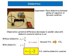
5) Capacitor with a Dielectric Up to this point we have calculated the capacitance assuming that there is no material in the space between the plates of capacitor. If you fill the space between the plates of a capacitor with a dielectric, which is an insulating material. It found that the capacitance increased by a numerical factor ke, which he called the dielectric constant of the insulating material. Table shows some dielectric materials and their dielectric constants. Fig. (a) show if the potential difference V between the plates of a capacitor is constant , as by battery B, the effect of a dielectric is to increase the charge q on the plates. Thus, the capacitance C increases. However, Fig. (b) show if the charge q on the capacitor plates is constant, as in this case, the effect of a dielectric is to reduce the potential difference V between the plate ke = C / C 0 V = V 0 / ke …. . (13)

5) Capacitor with a Dielectric In a region completely filled by a dielectric material of dielectric constant ke, all electrostatic equations containing the permittivity constant ε 0 are to be modified by replacing ε 0 with ke ε 0. Example: For a parallel-plate capacitor filled with dielectric , the capacitance is the magnitude of the electric field produced by a point charge inside a dielectric is given by this modified form the expression for the electric field just outside an isolated conductor immersed in a dielectric becomes

5) Capacitor with a Dielectric Sample Problem 11 A parallel-plate capacitor whose capacitance is 13. 5 p. F is charged by a battery to a potential difference 12. 5 V between its plates. The charging battery is now disconnected, and a porcelain slab (ke = 6. 5) is slipped between the plates. (a) What is the potential energy of the capacitor before the slab is inserted? (b) What is the potential energy of the capacitor–slab device after the slab is inserted? (c) What is work done here?

6) Dielectrics An Atomic View: when we put a dielectric in an electric field? There are two possibilities, depending on the type of molecule: 1. Polar dielectrics. The molecules of some dielectrics, like water, have permanent electric dipole moments. In such materials (called polar dielectrics), the electric dipoles tend to line up with an external electric field as in Fig. Because the molecules are continuously jostling each other as a result of their random thermal motion, this alignment is not complete, but it becomes more complete as the magnitude of the applied field is increased. The alignment of the electric dipoles produces an electric field that is directed opposite the applied field and is smaller in magnitude.

6) Dielectrics An Atomic View: when we put a dielectric in an electric field? There are two possibilities, depending on the type of molecule: 2. Nonpolar dielectrics. Regardless of whether they have permanent electric dipole moments, molecules acquire dipole moments by induction when placed in an external electric field. Figure a shows a nonpolar dielectric slab with no external electric field applied. In Fig. b, an electric field E 0 is applied via a capacitor, whose plates are charged as shown. The result is a slight separation of the centers of the positive and negative charge distributions within the slab, producing positive charge on one face of the slab and negative charge on the opposite face. The slab as a whole remains electrically neutral and—within the slab—there is no excess charge in any volume element. Figure c shows that the induced surface charges on the faces produce an electric field E’ in the direction opposite that of the applied electric field E 0. The resultant field E’ inside the dielectric (the vector sum of fields E 0 and E’ ) has the direction of E 0 but is smaller in magnitude.
 4 forces of nature
 Ib physics topic 5 question bank
 Electricity and magnetism lecture notes
 Magnetism jeopardy
 Sph3u electricity and magnetism
 Electromagnet experiment hypothesis
 Induced magnetic moment
 Grade 5 electricity and magnetism
 Electricity and magnetism
 Electricity and magnetism
 Electricity and magnetism
 Electricity and magnetism
 Electricity and magnetism
 How are static electricity and current electricity alike
 Static electricity and current electricity
 Current electricity
 Inductor in dc circuit
 Charge in series and parallel
 Capacitors and inductors
 Capacitor quiz
 Capacitance and dielectrics
 What are polar and nonpolar dielectrics
 Stressed oil volume theory is applicable when
 Treeing and tracking in solid dielectrics
 Conceptual physics magnetism
 Magnetism
 Fun with capacitors
