
HIGH VOLTAGE ENGINEERING EET 417 1 CHAPTER 4





- Slides: 55
HIGH VOLTAGE ENGINEERING EET 417 1
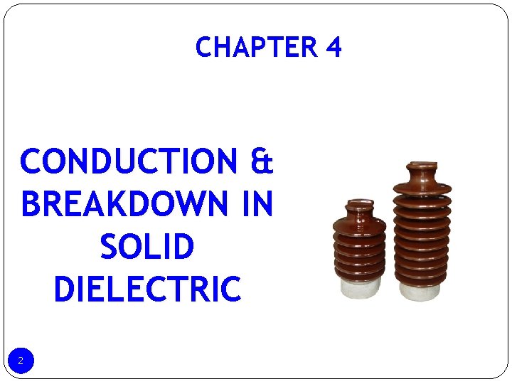
CHAPTER 4 CONDUCTION & BREAKDOWN IN SOLID DIELECTRIC 2
TOPIC OUTLINE 4. 1 INTRODUCTION 4. 2 INTRINSIC BREAKDOWN 4. 3 ELECTROMECHANICAL BREAKDOWN 4. 4 THERMAL BREAKDOWN 4. 5 BREAKDOWN OF SOLID DIELECTRICS IN PRACTICE 4. 6 BREAKDOWN IN COMPOSITE DILECTRICS 4. 7 SOLID DILECTRICS USED IN PRACTICE 3
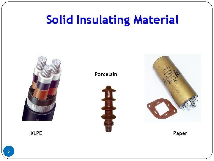
4. 1 INTRODUCTION Solid dielectric materials are used in all kinds of electrical apparatus and device to insulate one current carrying part from another when they operate at different voltages. Solid dielectric have higher breakdown strength compared to liquids and gases A good dielectric should have : • Low dielectric loss • High mechanical strength • Should be free from gaseous inclusions and moisture • Resistant to thermal and chemical deterioration Types of Solid insulating materials: • • 4 Organic materials (paper, wood and rubber) Inorganic materials (Mica, glass and porcelain and synthetic polymers)
Solid Insulating Material Porcelain XLPE 5 Paper
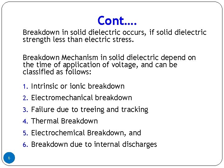
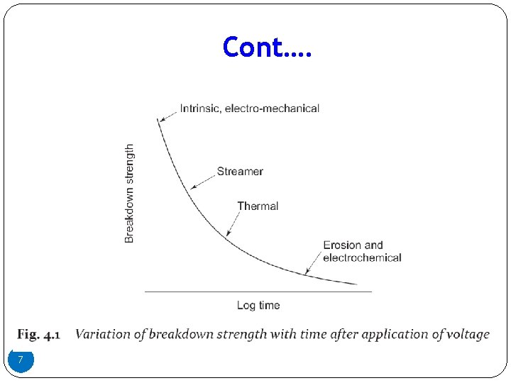
Cont…. Breakdown in solid dielectric occurs, if solid dielectric strength less than electric stress. Breakdown Mechanism in solid dielectric depend on the time of application of voltage, and can be classified as follows: 1. Intrinsic or ionic breakdown 2. Electromechanical breakdown 3. Failure due to treeing and tracking 4. Thermal Breakdown 5. Electrochemical Breakdown, and 6. Breakdown due to internal discharges 6
Cont…. 7
4. 2 Intrinsic Breakdown occurs if the applied on solid dielectric increases to 10 6 Volt/cm in short duration in order 10 -8 sec. This breakdown depends upon the presence of free electrons which are capable of migration through the lattice of the dielectric. Based on experiment the maximum electrical strength recorded is 15 MV/cm for Polyvinyl at -196 °C. The maximum strength usually obtainable ranges from 5 MV/cm to 10 MV/cm There are two types of intrinsic breakdown mechanism e. g Electronic Breakdown and Streamer Breakdown (avalanche). 8
4. 2. 1 Electronic Breakdown Assumed to be electronic in nature (occurs in time 10 -8 s) Initial density of conduction (free) electrons assumed to be large and electron-electron collisions occurs. When electric field is applied, electrons gain energy and cross the forbidden gap from the valency to the conduction band. This process repeated, more and more electrons available in conduction band, eventually leading to breakdown. 9
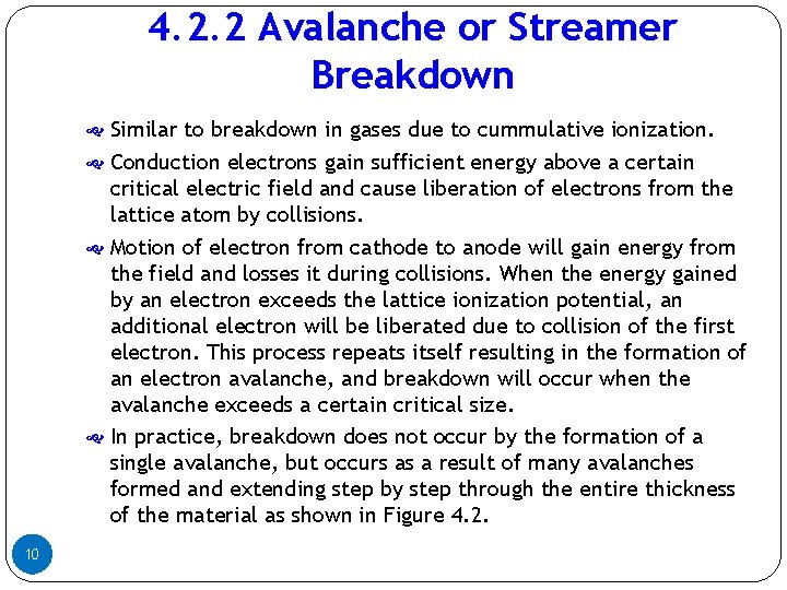
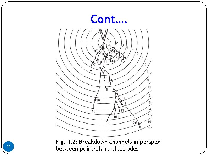
4. 2. 2 Avalanche or Streamer Breakdown Similar to breakdown in gases due to cummulative ionization. Conduction electrons gain sufficient energy above a certain critical electric field and cause liberation of electrons from the lattice atom by collisions. Motion of electron from cathode to anode will gain energy from the field and losses it during collisions. When the energy gained by an electron exceeds the lattice ionization potential, an additional electron will be liberated due to collision of the first electron. This process repeats itself resulting in the formation of an electron avalanche, and breakdown will occur when the avalanche exceeds a certain critical size. In practice, breakdown does not occur by the formation of a single avalanche, but occurs as a result of many avalanches formed and extending step by step through the entire thickness of the material as shown in Figure 4. 2. 10
Cont…. 11 Fig. 4. 2: Breakdown channels in perspex between point-plane electrodes
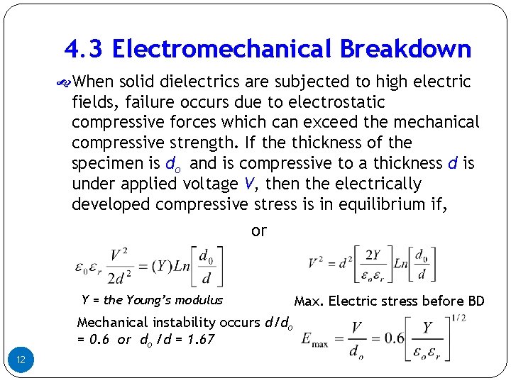
4. 3 Electromechanical Breakdown When solid dielectrics are subjected to high electric fields, failure occurs due to electrostatic compressive forces which can exceed the mechanical compressive strength. If the thickness of the specimen is do and is compressive to a thickness d is under applied voltage V, then the electrically developed compressive stress is in equilibrium if, or Y = the Young’s modulus Mechanical instability occurs d/do = 0. 6 or do /d = 1. 67 12 Max. Electric stress before BD
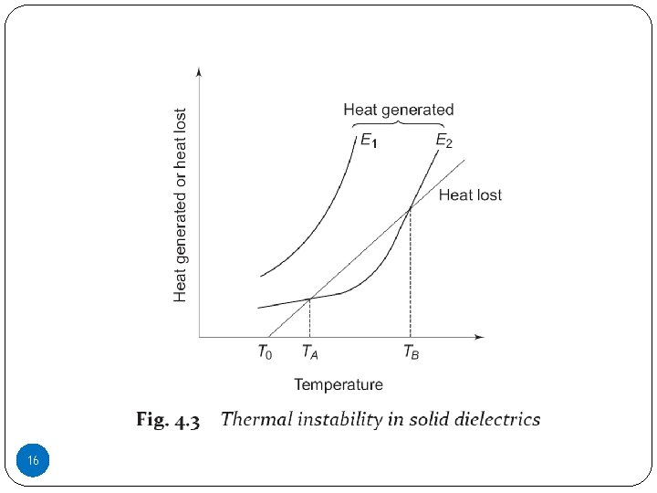
4. 4 Thermal Breakdown When an electric field is applied to a dielectric, conduction current, however small it may be, flows through the material. The current heats up the specimen and the temperature rises. The heat generated is transferred to the surrounding medium by conduction through the solid dielectric and by radiation from its outer surfaces. Equilibrium is reached when the heat used to raise the temperature of the dielectric, plus the heat radiated out, equals the heat generated. 13
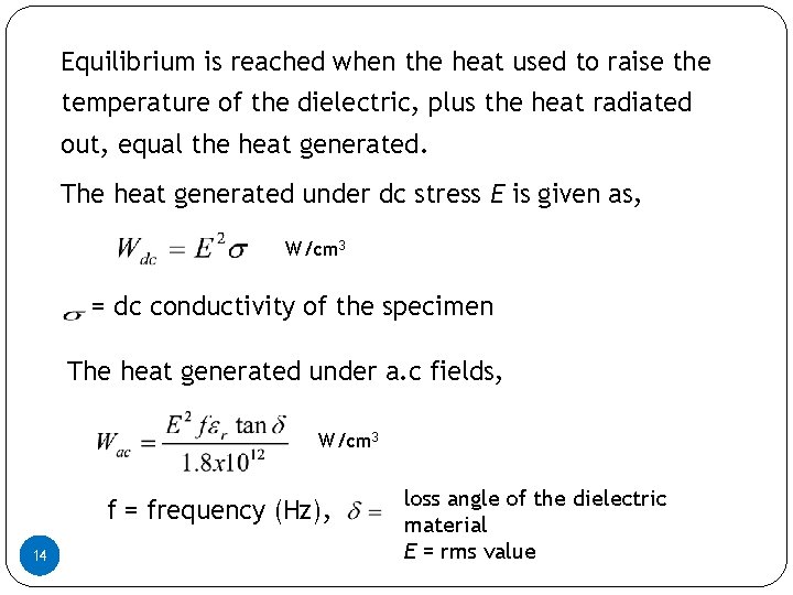
Equilibrium is reached when the heat used to raise the temperature of the dielectric, plus the heat radiated out, equal the heat generated. The heat generated under dc stress E is given as, W/cm 3 = dc conductivity of the specimen The heat generated under a. c fields, W/cm 3 f = frequency (Hz), 14 14 loss angle of the dielectric material E = rms value
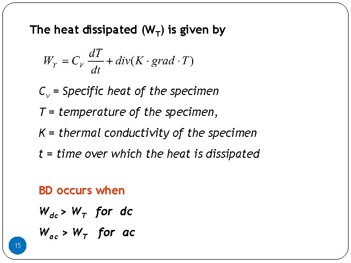
The heat dissipated (WT) is given by Cv = Specific heat of the specimen T = temperature of the specimen, K = thermal conductivity of the specimen t = time over which the heat is dissipated BD occurs when Wdc > WT for dc Wac > WT for ac 15 15
16 16
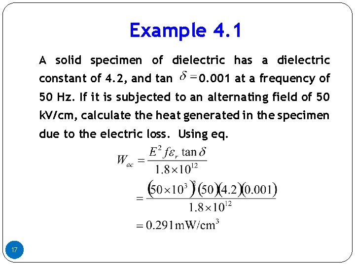
Example 4. 1 A solid specimen of dielectric has a dielectric constant of 4. 2, and tan 0. 001 at a frequency of 50 Hz. If it is subjected to an alternating field of 50 k. V/cm, calculate the heat generated in the specimen due to the electric loss. Using eq. 17
4. 5 Breakdown of Solid Dielectric in Practice There are certain type of breakdown which do not come under either intrinsic breakdown or thermal breakdown but occur after prolonged time, eg. breakdown due to tracking in which dry conducting tracks are formed on the surface of the insulation. These tracks act as conducting path - leading to gradual breakdown. Another type in this category is electrochemical breakdown caused by chemical transformation such as electrolysis, formation of ozone etc. Failure also occurs due to partial discharges which are brought about in the air pockets inside the insulation. This breakdown is very important in the impregnated paper insulation used in HV cables and capacitors. 18
4. 5. 1 Chemical and Electrochemical Breakdown In presence of air and other gases, dielectric materials undergo chemical changes when subjected to continuous electrical stresses. Some of the important chemical reactions that occur are: Oxidation : In the presence of air or oxygen, materials such as rubber and polyethylene undergo oxidation giving rise to surface cracks. Hydrolysis : When moisture or water vapour is present on the surface of the solid dielectric, hydrolysis occurs and the materials lose their electrical and mechanical properties. Materials like paper, cotton tape and other cellulose materials deteriorate very rapidly due to hydrolysis. Chemical Action : Progressive chemical degradation can occur due to a variety of processes such as chemical instability at high temperature, oxidation, cracking and hydrolysis. 19
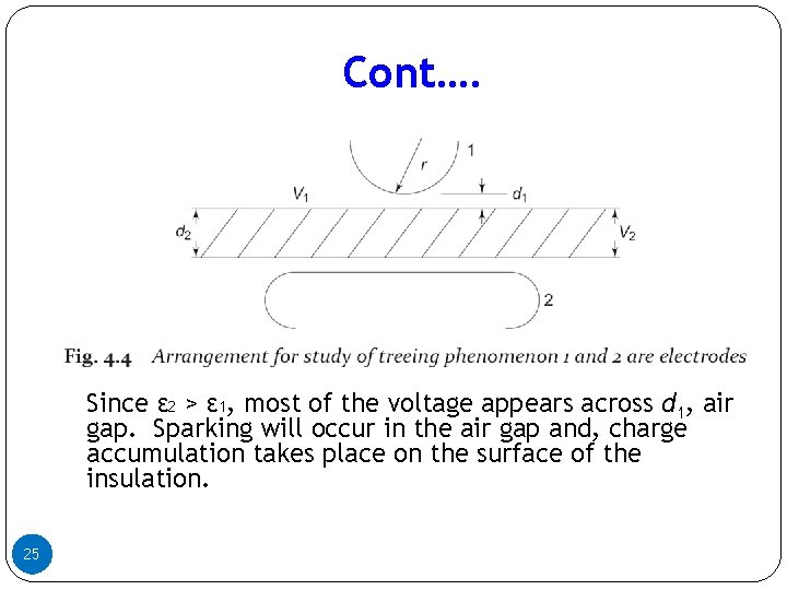
4. 5. 2 Breakdown Due to Treeing and Tracking When solid dielectric subjected to electrical stresses for a long time, two kinds of visible marking are observed. a) The presence of a conducting path across the surface of insulation b) Mechanism whereby leakage current passes thru the conducting path, finally leading to the formation of spark. 20
Cont…. Tracking is the formation of a continuous conducting path across the surface of the insulation mainly due to surface erosion under voltage application. In practice, the surface of solid dielectric material always having the conducting film, which is formed due to moisture. On application of voltage, the film starts conducting, resulting in generation of heat, and the surface starts becoming dry. The conducting film becomes separate due to drying, and so sparks are drawn damaging the dielectric surface. With organic insulating material, the dielectric carbonizes at the region of sparking, and carbonized regions act as permanent conducting channels. This is a cumulative process, and insulation failure occurs when carbonized tracks bridge the distance between the electrodes. 21
Cont…. The spreading of a spark channels during tracking, in the form of the branches of the tree is called treeing. Treeing occurs due to the erosion of material at the tips of the spark. Erosion results in the roughening of the surface and hence becomes a source of dirt contamination. Tracking occurs even at very low voltages of the order of a bout 100 V, whereas treeing requires high voltage 22
Cont…. Treeing can be prevented by having clean, dry, and undamaged surface and a clean environment. The material chosen should be resistant to tracking. Standard testing for tracking: IEC 587 (1984), ASTM-D- 495 (1973) etc. Sometimes moistures repellant greases are used. But this needs frequent cleaning and regressing. Treeing phenomenon is observed in capacitors and cables, and extensive work is being done to investigate the real and natural causes of this phenomenon. 23
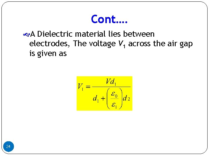
Cont…. A Dielectric material lies between electrodes, The voltage V 1 across the air gap is given as 24
Cont…. Since ε 2 > ε 1, most of the voltage appears across d 1, air gap. Sparking will occur in the air gap and, charge accumulation takes place on the surface of the insulation. 25
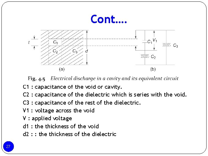
4. 5. 3 Breakdown Due to Internal Discharge Solid insulating materials contain voids or cavities within the medium or at the boundaries between the dielectric and the electrodes. These voids are generally filled with a medium of lower dielectric strength, and the dielectric constant of the medium in the voids is lower than that insulation. Hence the electric field higher than that across the dielectric. Therefore, even under normal working voltages the field in the voids may exceed their breakdown value, and breakdown occur. 26
Cont…. C 1 : capacitance of the void or cavity. C 2 : capacitance of the dielectric which is series with the void. C 3 : capacitance of the rest of the dielectric. V 1 : voltage across the void V : applied voltage d 1 : the thickness of the void d 2 : : the thickness of the dielectric 27
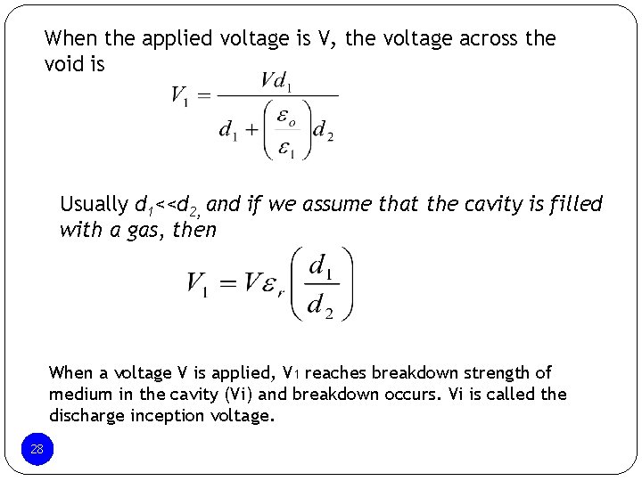
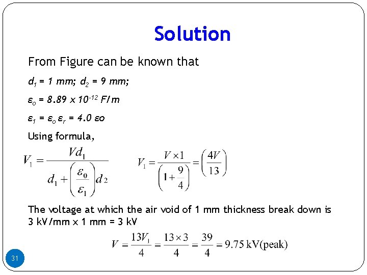
When the applied voltage is V, the voltage across the void is Usually d 1<<d 2, and if we assume that the cavity is filled with a gas, then When a voltage V is applied, V 1 reaches breakdown strength of medium in the cavity (Vi) and breakdown occurs. Vi is called the discharge inception voltage. 2828
2929 Internal discharge
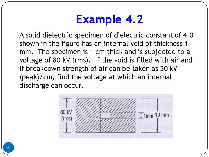
Example 4. 2 A solid dielectric specimen of dielectric constant of 4. 0 shown in the figure has an internal void of thickness 1 mm. The specimen is 1 cm thick and is subjected to a voltage of 80 k. V (rms). If the void is filled with air and if breakdown strength of air can be taken as 30 k. V (peak)/cm, find the voltage at which an internal discharge can occur. 30
Solution From Figure can be known that d 1 = 1 mm; d 2 = 9 mm; εo = 8. 89 x 10 -12 F/m ε 1 = εo εr = 4. 0 εo Using formula, The voltage at which the air void of 1 mm thickness break down is 3 k. V/mm x 1 mm = 3 k. V 31
4. 6 Breakdown in Composite Dielectric Composite materials are composed of different chemical substances or with materials of different compositions in series or parallel. Chemical reactions occurs when a voltage is applied to them and there will be a substantial increase, if the applied voltage is continuous and high temperature are present. These conditions, the composites undergo chemical deterioration leading to reduction in both the electrical and mechanical strength. 32
Cont…. Example composite Solid/solid : Cable Solid/Liquid : Capacitor, transformer, oil- filled switchgear Solid/SF 6 : Circuit breaker etc 33
Cont…. Composite Dielectric Properties of the layered construction a) Effect of multiple layers b) Effect of layer thickness c) Effect of Interfaces 34
Cont…. Effect of multiple layers The simplest dielectric composite consist of two layers of the same material. Advantages Have a higher dielectric strength than single sheet of the same total thickness Have a wide variation in dielectric strength values at different points on its surface 35
Cont…. Effect of Layer Thickness Increase in layer thickness gives increased breakdown Voltage breakdown channels occur at the interface only not directly through another layer. Layered construction is very important in the case of insulating paper since the paper thickness itself varies from point to point and consequently the dielectric strength across its surface is not homogeneous. 36
Cont…. The differences in the thickness impart a rough surface to paper which can produce an electric field stress comparable to that of the discharge channel. The rough surface of the paper also helps in better impregnation when tightly wound. The existence of areas with lower thickness in the paper can cause BD at these point at considerably lower voltage 37
Effect of Interface Discharge usually occur at the interfaces and the magnitude of the discharge depend on the associated surface resistance and capacitance. If the surface conductivity increase, the discharge magnitude also increases, resulting in damage to the dielectric. The others composite dielectric properties • The discharge inception voltage depends on the thickness of the solid dielectric, the dielectric constant of the both • The difference in the dielectric constant between the liquid and solid does not significantly affect the rate of change of electric field at the electrode edge 38
Mechanism of Breakdown in Composite Dielectric. Short-term breakdown, If the electric field stresses are very high, failure may occur in seconds or even faster without any substantial damage to the insulating surface prior to BD. Its due to result from one or more discharges when the applied voltage is close to the breakdown value. rapidly when the electric field in the insulation is such that assists the Breakdown occurs more charged particles in the discharge to penetrate into insulation. 39
Cont…. Breakdown, is also the ageing of insulation. This BD result in process thermal and partial discharge. Partial discharge normally occur within volume of the composite insulation systems. The charge accumulation and conduction on the surface of the insulation also contributes significantly toward the ageing and failure of insulation. i) Ageing and breakdown due to partial discharge ii) Ageing and breakdown due to accumulation of charge on insulator surface. 40
Solid Dielectrics Used in Practice Organic materials Inorganic materials Synthetic polymers 41
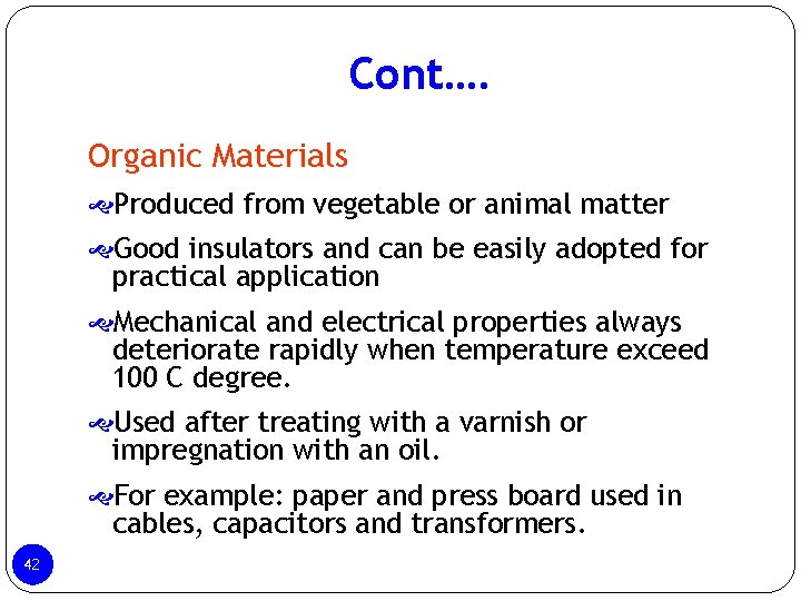
Cont…. Organic Materials Produced from vegetable or animal matter Good insulators and can be easily adopted for practical application Mechanical and electrical properties always deteriorate rapidly when temperature exceed 100 C degree. Used after treating with a varnish or impregnation with an oil. For example: paper and press board used in cables, capacitors and transformers. 42
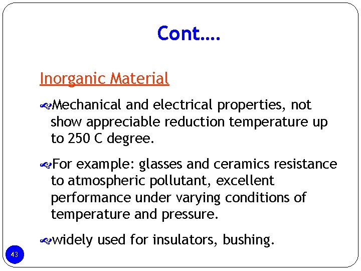
Cont…. Inorganic Material Mechanical and electrical properties, not show appreciable reduction temperature up to 250 C degree. For example: glasses and ceramics resistance to atmospheric pollutant, excellent performance under varying conditions of temperature and pressure. widely used for insulators, bushing. 43
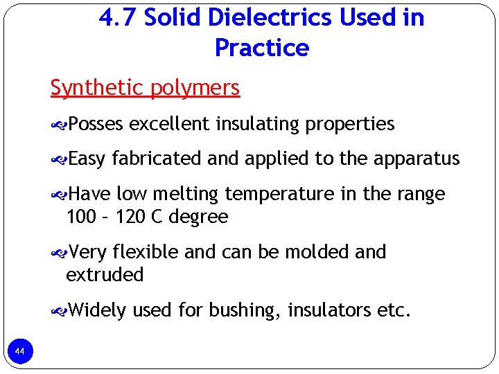
4. 7 Solid Dielectrics Used in Practice Synthetic polymers Posses excellent insulating properties Easy fabricated and applied to the apparatus Have low melting temperature in the range 100 – 120 C degree Very flexible and can be molded and extruded Widely used for bushing, insulators etc. 44
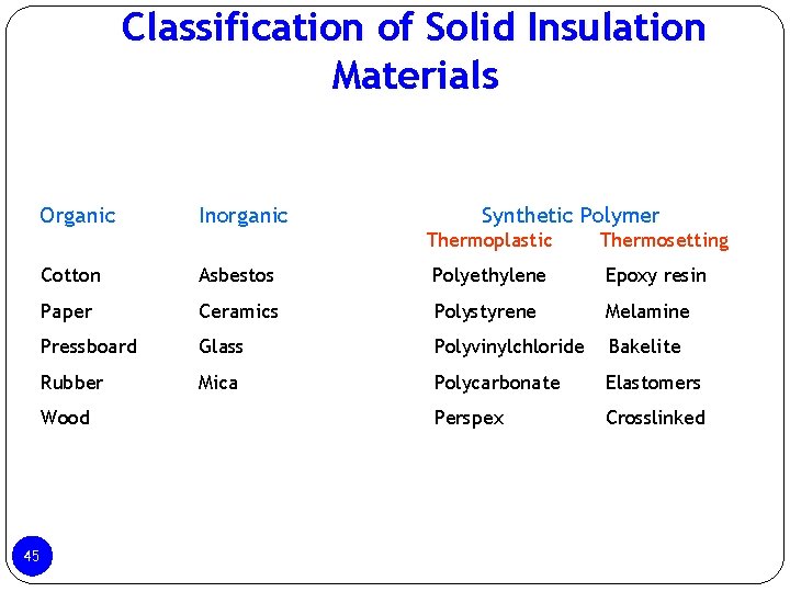
Classification of Solid Insulation Materials Organic Inorganic Synthetic Polymer Thermoplastic Cotton Asbestos Polyethylene Epoxy resin Paper Ceramics Polystyrene Melamine Pressboard Glass Polyvinylchloride Bakelite Rubber Mica Polycarbonate Elastomers Perspex Crosslinked Wood 45 Thermosetting
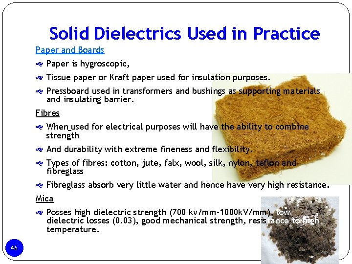
Solid Dielectrics Used in Practice Paper and Boards Paper is hygroscopic, Tissue paper or Kraft paper used for insulation purposes. Pressboard used in transformers and bushings as supporting materials and insulating barrier. Fibres When used for electrical purposes will have the ability to combine strength And durability with extreme fineness and flexibility. Types of fibres: cotton, jute, falx, wool, silk, nylon, teflon and fibreglass Fibreglass absorb very little water and hence have very high resistance. Mica Posses high dielectric strength (700 kv/mm-1000 k. V/mm), low dielectric losses (0. 03), good mechanical strength, resistance to high temperature. 46
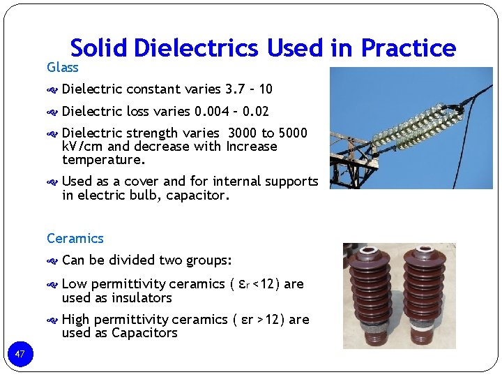
Solid Dielectrics Used in Practice Glass Dielectric constant varies 3. 7 – 10 Dielectric loss varies 0. 004 – 0. 02 Dielectric strength varies 3000 to 5000 k. V/cm and decrease with Increase temperature. Used as a cover and for internal supports in electric bulb, capacitor. Ceramics Can be divided two groups: Low permittivity ceramics ( used as insulators εr <12) are High permittivity ceramics ( εr >12) are used as Capacitors 47
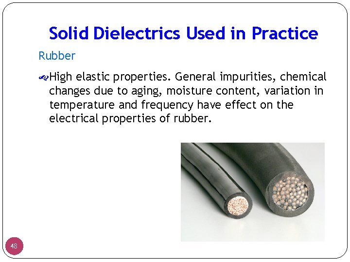
Solid Dielectrics Used in Practice Rubber High elastic properties. General impurities, chemical changes due to aging, moisture content, variation in temperature and frequency have effect on the electrical properties of rubber. 48
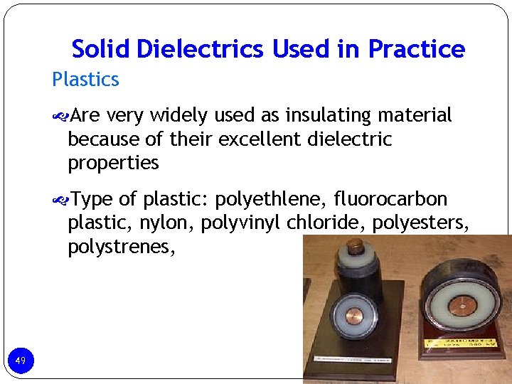
Solid Dielectrics Used in Practice Plastics Are very widely used as insulating material because of their excellent dielectric properties Type of plastic: polyethlene, fluorocarbon plastic, nylon, polyvinyl chloride, polyesters, polystrenes, 49
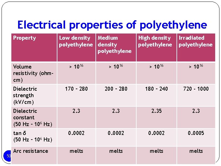
Electrical properties of polyethylene Property Volume resistivity (ohmcm) High density polyethylene Irradiated polyethylene > 1016 170 – 280 200 – 280 180 – 240 720 - 1000 Dielectric constant (50 Hz – 106 Hz) 2. 35 2. 3 tan δ (50 Hz – 106 Hz) 0. 0002 0. 0005 Arc resistance melts Dielectric strength (k. V/cm) 50 Low density Medium polyethylene density polyethylene
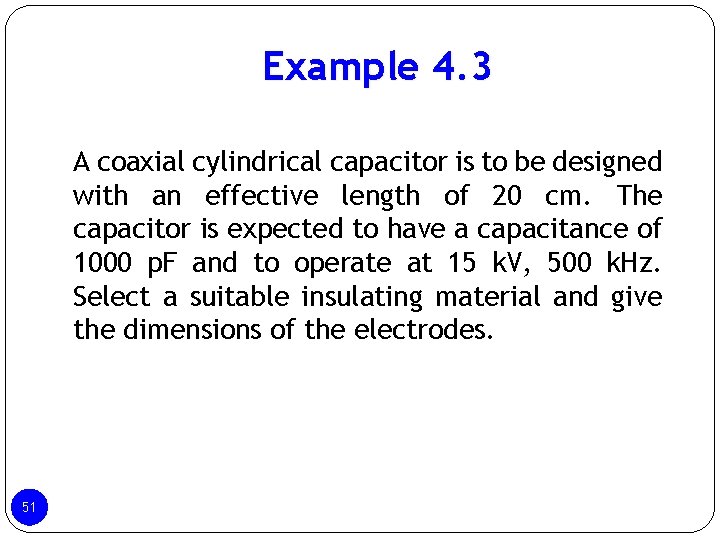
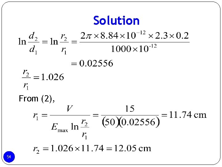
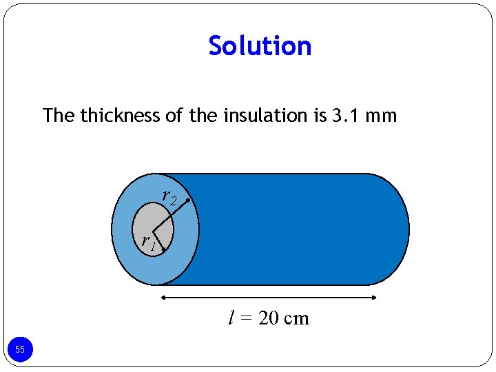
Example 4. 3 A coaxial cylindrical capacitor is to be designed with an effective length of 20 cm. The capacitor is expected to have a capacitance of 1000 p. F and to operate at 15 k. V, 500 k. Hz. Select a suitable insulating material and give the dimensions of the electrodes. 51
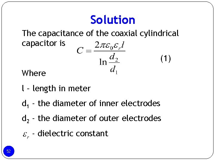
Solution The capacitance of the coaxial cylindrical capacitor is (1) Where l – length in meter d 1 - the diameter of inner electrodes d 2 - the diameter of outer electrodes - dielectric constant 52
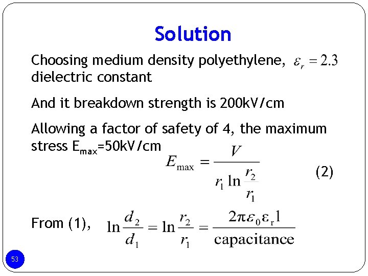
Solution Choosing medium density polyethylene, dielectric constant And it breakdown strength is 200 k. V/cm Allowing a factor of safety of 4, the maximum stress Emax=50 k. V/cm (2) From (1), 53
Solution From (2), 54
Solution The thickness of the insulation is 3. 1 mm r 2 r 1 l = 20 cm 55