Electrical Engineering Principle TOPIC II MAGNETISM AND ELECTROMAGNETIC


")
 of a magnet")


 G C")


 Since AB moves to the left, direction of the induced current as")


- Slides: 41
Electrical Engineering Principle TOPIC II MAGNETISM AND ELECTROMAGNETIC by: baizura
II. MAGNETISM AND ELECTROMAGNETIC The knowledge that students can obtain from this topic are: a. The concept of magnetism and electromagnetism with simple explanation. b. Laws and rule that related to magnetic and electric field. c. Understanding of magnetic hysteresis and hysteresis loop
2. 1. Magnetic Field. The pointer of a compass is - from steel - call a permanent magnet S N The earth’s North Pole (or N) and the other end is called the south (or S). Fig. 2. 1 Suspended permanent magnet
• Magnetism is a force field that acts on some materials (magnetic materials) but not on other materials (non magnetic materials). • Magnetic field around a bar magnet • Two “poles” dictated by direction of the field • Opposite poles attract (aligned magnetic field) • Same poles repel (opposing magnetic field)
• By convention, flux lines leave the northseeking end (N) of a magnet and enter its south-seeking end (S).
The idea of lines of magnetic flux. Fig. 2. 2. Use of steel filings for determining distribution of magnetic field
2. 2. Magnetic field due to an electric current. I N S The needle was deflected clockwise or anticlockwise, depending upon the direction of the current. A phenomenon discovered by Oersted at Copenhagen in 1820. Fig. 2. 3 Oersted’s experiment
Cu rr e nt The lines of magnetic flux Conductor Fig. 2. 4 Magnetic flux due to current in a straight conductor
Approaching current Note the interesting convention for showing the direction of current flow in a conductor. Departing current Fig. 2. 5. Current convention.
2. 3. Faraday’s Law of Electromagnetic Induction. • First Law It states: - Whenever the magnetic flux linked with a circuit changes, an e. m. f. is always induced in it. Or Whenever a conductor cuts magnetic flux, an e. m. f. is induced in that conductor. • Second Law It states : - The magnitude the induced e. m. f. is equal to the rate of change of flux linkages.
Explanation : Suppose a coil has N turns and flux trough it changes from an initial value of Ф 1 webers to the final value of Ф 2 webers in time t second. Initial flux linkages = NФ 1 Final flux linkages = NФ 2 The induced e. m. f = e = Or e= volt
2. 4 Fleming’s Right-hand Rulec M O T I O N S N FIELD F EM
I. e. dynamically induced e. m. f. A A v B B θ v (a) (b) e = Blv volt e = Blv sin θ volt B= flux density l = length of conductor v = velocity θ = angle
2. 5 Lenz's Law C N A N D B S (a) G C S N (b) G A S
i. e. Statically Induced E. M. F or or e = L ; Volt ; e. M = Volt Where : L = Coefficient of self- inductance M= Coefficient of mutual inductance
2. 7 Magnetic Hysterisis H= NI/l produced by solenoid- called magnetizing force The value of H can be increased or decreased by increasing or decreasing current through the coil. Fig. 2. 11 The hysterisis curve
2. 8 Hysteresis Loop
2. 9 Variations in Hysteresis Curves
AREA OF HYSTERISIS LOOP l = mean of iron bar. A = its area of cross section N= No. of turns of wire of the solenoid. B = flux density
The power of rate of expenditure of energy Watt = e. I watt = Energy spent in time ‘dt’ = Where; Ф = BA e= Volt H = NI/l e= Volt
Total network done for one cycle of magnetization is Joule Hence So, = area of the loop i. e. the area between B/H curve and the B-axis. work done/cycle = A. l x (area of the loop) joule. Now A. l. = volume of material. So net work done/cycle/m 3 = (loop area ) joule. Or Wh = (area of B/H loop) joule/m 3/cycle.
Example 2. 1 The field coils of a 6 -pole dc generator each have 500 turns, are connected in series. When the field is excited, there is a magnetic flux of 0. 02 Wb/pole. If the field circuit is opened in 0. 02 second and the residual magnetism is 0. 002 Wb/pole. Calculate the average voltage which is induced across the field terminals. In which direction is this voltage directed relative to the direction of the current.
Solution • Total number of turn, N = 6 x 500 = 3000 • Total initial flux = 6 x 0. 02 = 0. 12 Wb • Total residual flux = 6 x 0. 002 = 0. 012 Wb • Change in flux, d Φ = 0. 12 – 0. 012 = 0. 108 Wb • Time of opening the circuit, dt = 0. 02 • Induced e. m. f = = 3000 x = 16, 200 V second
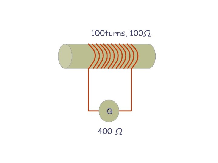
Example 2. 2 A coil of resistance 100 Ω is placed in a magnetic field of 1 m. Wb. The coil has 100 turns and galvanometer of 400 Ω resistances is connected in series with it. Find the average e. m. f and the current if the coil is moved in 1/10 th second from the given field to a field of 0. 2 m. Wb.
Solution. Here dф = 1 -0. 2 = 0. 8 m. Wb = 0. 8 x 10 -3 Wb dt = 1/10 e = 0. 1 second ; N = 100 x 0. 8 x 10 -3 /0. 1 = 0. 8 V Total circuit resistance = 100 + 400 = 500 Ω Current induced = 0. 8 / 500 = 1. 6 x 10 -3 A = 1. 6 m. A
Example 2. 3 A conductor of length 1 meter moves at right angles to a uniform magnetic field of flux density 1. 5 Wb/m 2 with a velocity of 50 meters /second. Calculate the e. m. f induced in it. Find also the value of induced e. m. f when the conductor moves at an angle of 30 o to the direction of the field.
1 meter 30 o 1. 5 Wb/m 2 50 m /s
Solution Here B = 1. 5 Wb/m 2 ; l = 100 cm = 1 m ; v = 50 m/s Now e = B. l. v = 1. 5 x 1 x 50 = 75 Volt In the second case θ = 30 o sin 30 o = 0. 5 e = 75 x 0. 5 = 37. 5 Volt
Example 2. 4 A conducting rod AB makes contact with metal rails AD and BC which are 50 cm apart in uniform magnetic field B = 1. 0 Wb/m 2 perpendicular to the plane ABCD. The total resistance (assumed constant) of the circuit ABCD is 0. 4 Ω a). What is the direction and magnitude of the e. m. f induced in the rod when it is moved to the left with velocity of 8 m/s ? b). What force is required to keep the rod in motion? c). Compare the rate at which mechanical work is done by the force F with the rate of development of electric power in the circuit.
Solution a) Since AB moves to the left, direction of the induced current as found by applying Fleming’s left hand rule, is from A to B. Magnitude of the induced e. m. f is given by. e = B. l. v Volt = 1 x 0. 5 x 8 = 4 Volt. b) Current through AB = 4 / 0. 4 10 A. Force in AB i. e. F = B. I. l = 1 x 10 x 0. 5 = 5 N. The direction of this force, as found by applying Fleming left hand rule, is to the right. c) Rate of doing mechanical work = F x v = 5 x 8 = 40 j/s or W Electric power produced = e. I = 4 x 10 = 40 W From the above, it is obvious that the mechanical work done in moving the conductor against force F is converted into electric energy.
Example 2. 5 In a 4 -pole dynamo, the flux per pole is 15 m. Wb. Calculate the average e. m. f induced in one of the armature conductors if armature is driven at 600 rpm.
Solution It should be noted that each time the conductors passes under a pole (whether N or S) it cuts a flux of 15 m. Wb. Hence, total flux cut in one revolution is 15 x 4 = 60 m. Wb. Since conductor is rotating at 600/60 = 10 r. p. s Time taken for one revolution is 1/10 = 0. 1 second average e. m. f generated = Volt. Here N = 1 ; dф = 60 m. Wb = 6 x 10 -2 Wb ; dt = 0. 1 second. e = 1 x 6 x 10 -2 / 0. 1 = 0. 6 Volt.
Example 2. 6 The field winding of a d. c electromagnet is wound with 960 turns and has resistance of 50 Ω. When the exciting voltage is 230 V, the magnetic flux linking the coil is 0. 005 Wb. Calculate the self inductance of the coil and the energy stored in the magnetic field.
Solution henry Current through coil = 230 / 50 = 4. 6 A ф = 0. 005 Wb N = 960 L = ( 960 x 0. 005 ) / 4. 6 = 1. 0435 H. Energy stored = ½ L I 2 = ½ x 1. 0435 x 4. 62 = 11. 87 J.
Example 2. 7 Two identical coils X and Y of 1, 000 turns each line in parallel planes that 80% of flux produces a flux of 0. 05 m. Wb in it and current flows in the Coil X is 5 A, find the mutual inductance between X and Y.
Solution Flux produced in X = 0. 05 m. Wb = 0. 05 x 10 -3 Wb Flux linked with Y = 0. 005 x 10 -3 x 0. 8 = 0. 04 x 10 -3 Wb. M = (1000 x 0. 04 x 10 -3) / 5 = 8 x 10 -3 H
Example 2. 8 The hysteresis loop of a sample of sheet steel subjected to a maximum flux density of 1. 3 Wb/m 2 has an area of 93 cm 2, the scale being 1 cm = 0. 1 Wb/m 2 and 1 cm = 50 AT/m. Calculate the hysterisis loop in watts when 1500 cm 3 of the same material is subjected to an alternating flux density of 1. 3 Wb/ m 2 peak value at a frequency of 65 Hz
Solution Where 1 cm = 0. 1 Wb/m 2 and 1 cm = 50 AT/m For area of 93 cm 2 Loss = xy (area of B/H loop) j/m 3/cycle. = 0. 1 x 50 x 93 = 465 j/m 3/cycle. Volume = 1500 cm 3 = 15 x 10 -4 m 3 No of reversals / second = 65 Wh = 465 x 15 x 10 -4 x 65 j/s = 45. 3 W. Note. The given value of Bmax = 1. 3 Wb/m 3 is not required for solution
Example 2. 9 Calculate the hourly loss of energy in k. Wh in a specimen of iron, the hysteresis loop of which is equivalent in area to 250 j/m 3 Frequency 50 Hz, specific gravity of iron 7. 5 kg/dm 3 for weight of specimen 10 kg.
Solution Hysteresis loop = 250 j/m 3/ cycle Mass of iron = 10 kg Volume of a specimen = 10/7. 5 x 10³ m 3 = 10 -2 / 7. 5 m 3 No. of cycles of reversals / hr = 60 x 50 = 3000. Loss/hour = 250 x (10 -2 / 7. 5) x 3000 = 1000 j = 1000/(36 x 105) = 27. 8 x 10 -5 k. Wh.