EE 365 Adders Multipliers ReadOnly Memories 1 Equality
- Slides: 30
EE 365 Adders Multipliers Read-Only Memories 1
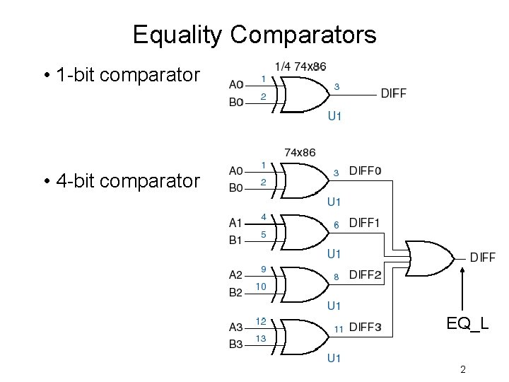
Equality Comparators • 1 -bit comparator • 4 -bit comparator EQ_L 2
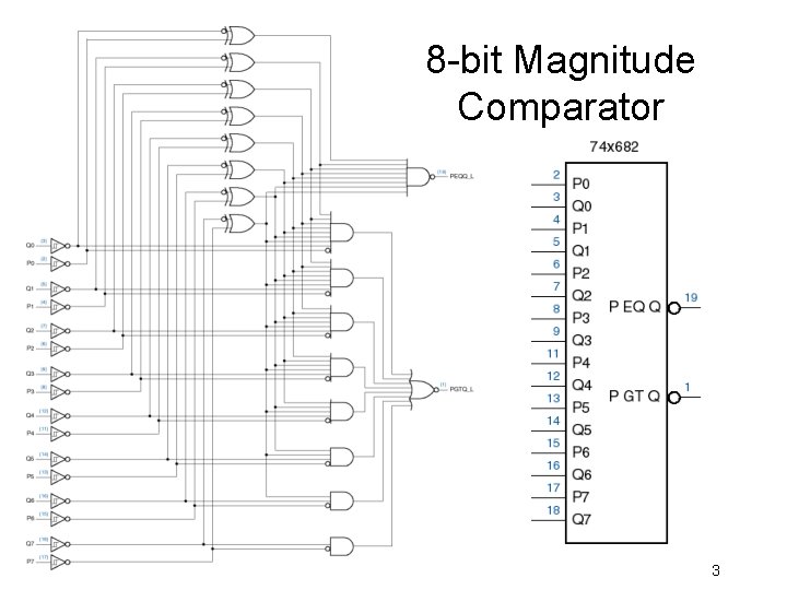
8 -bit Magnitude Comparator 3
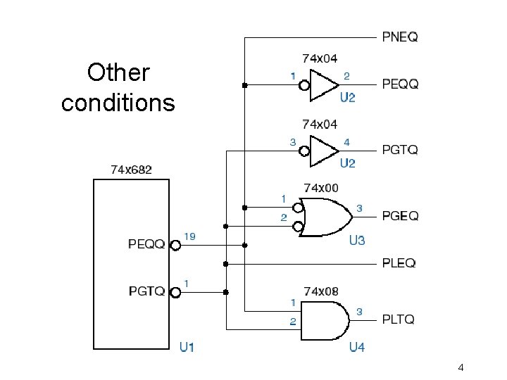
Other conditions 4
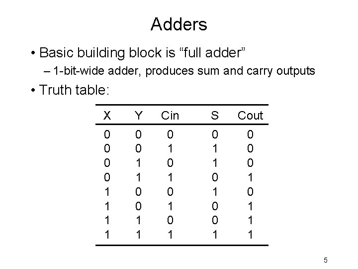
Adders • Basic building block is “full adder” – 1 -bit-wide adder, produces sum and carry outputs • Truth table: X Y Cin S Cout 0 0 1 1 0 1 0 1 0 1 1 0 0 0 1 1 1 5
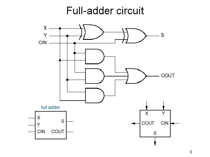
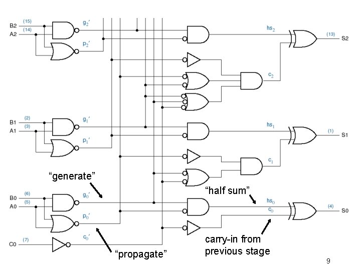
Full-adder circuit 6
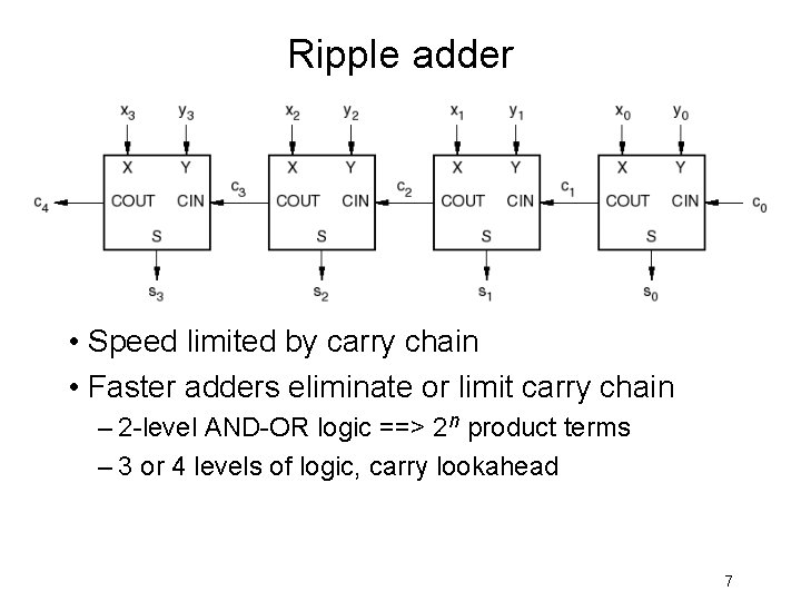
Ripple adder • Speed limited by carry chain • Faster adders eliminate or limit carry chain – 2 -level AND-OR logic ==> 2 n product terms – 3 or 4 levels of logic, carry lookahead 7
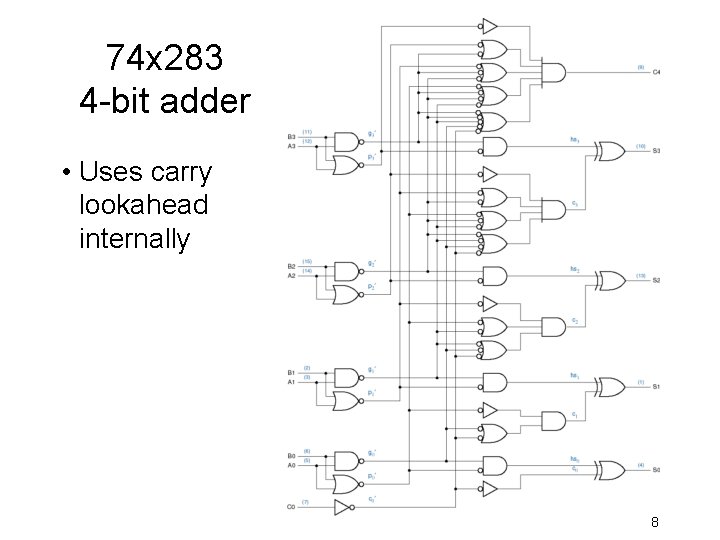
74 x 283 4 -bit adder • Uses carry lookahead internally 8
“generate” “half sum” “propagate” carry-in from previous stage 9
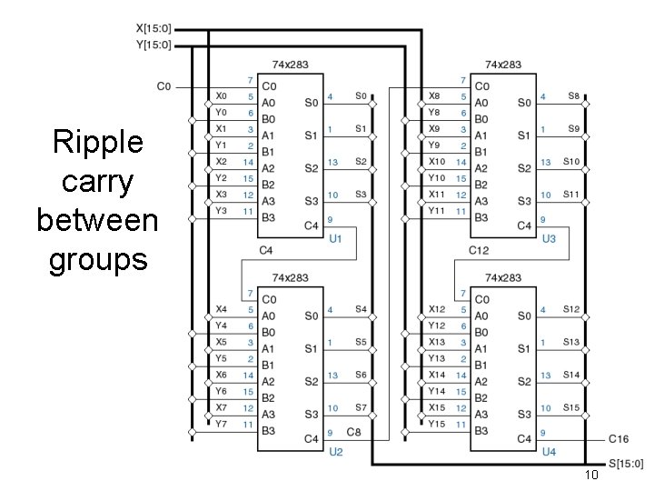
Ripple carry between groups 10
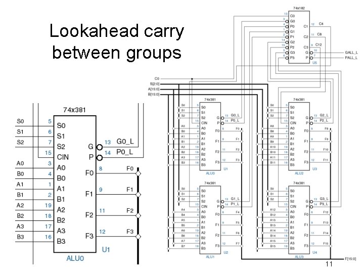
Lookahead carry between groups 11
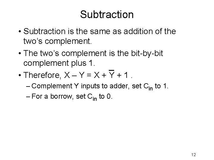
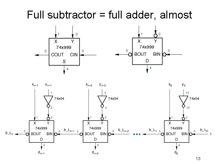
Subtraction • Subtraction is the same as addition of the two’s complement. • The two’s complement is the bit-by-bit complement plus 1. • Therefore, X – Y = X + Y + 1. – Complement Y inputs to adder, set Cin to 1. – For a borrow, set Cin to 0. 12
Full subtractor = full adder, almost 13
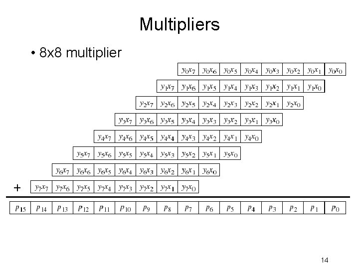
Multipliers • 8 x 8 multiplier 14
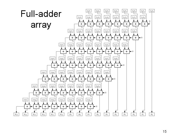
Full-adder array 15
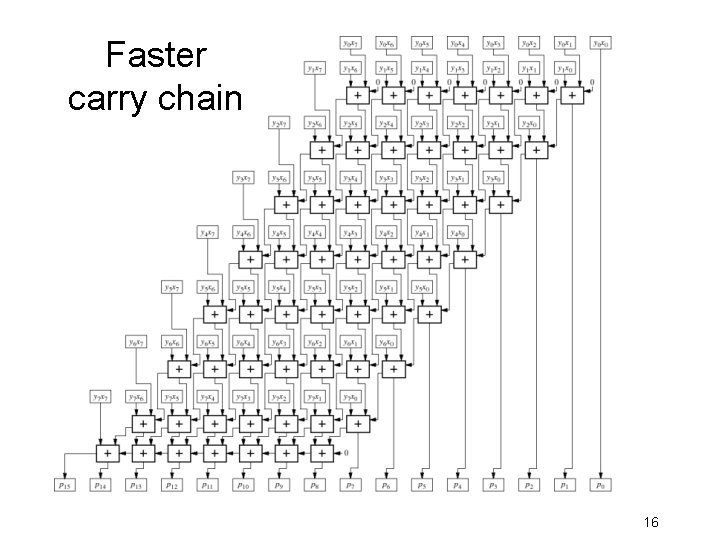
Faster carry chain 16
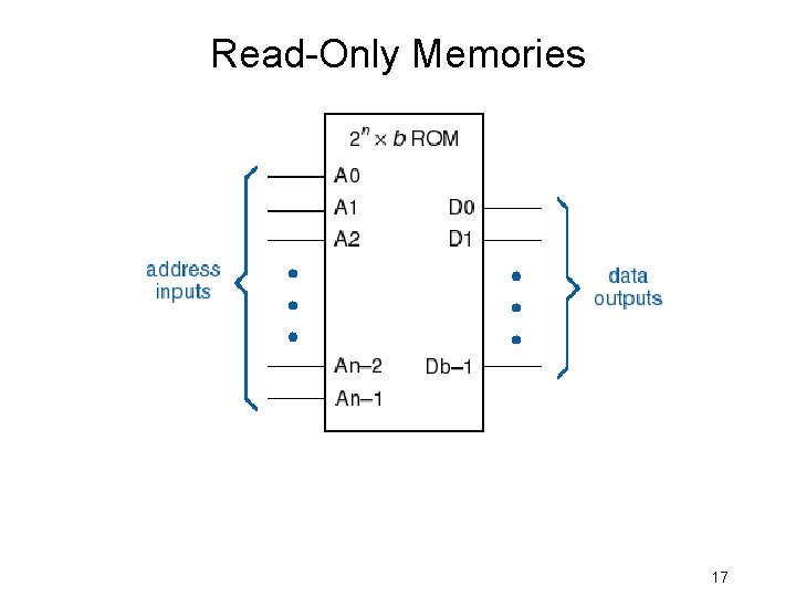
Read-Only Memories 17
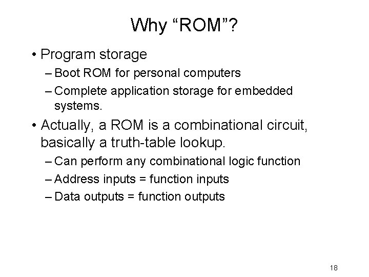
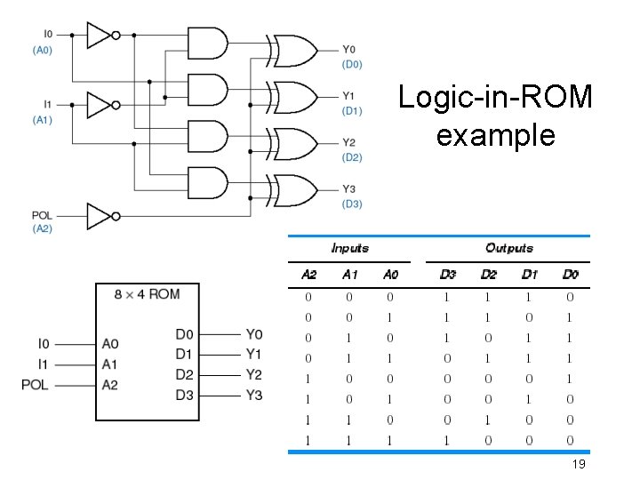
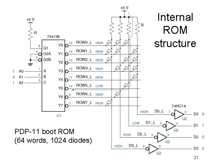
Why “ROM”? • Program storage – Boot ROM for personal computers – Complete application storage for embedded systems. • Actually, a ROM is a combinational circuit, basically a truth-table lookup. – Can perform any combinational logic function – Address inputs = function inputs – Data outputs = function outputs 18
Logic-in-ROM example 19
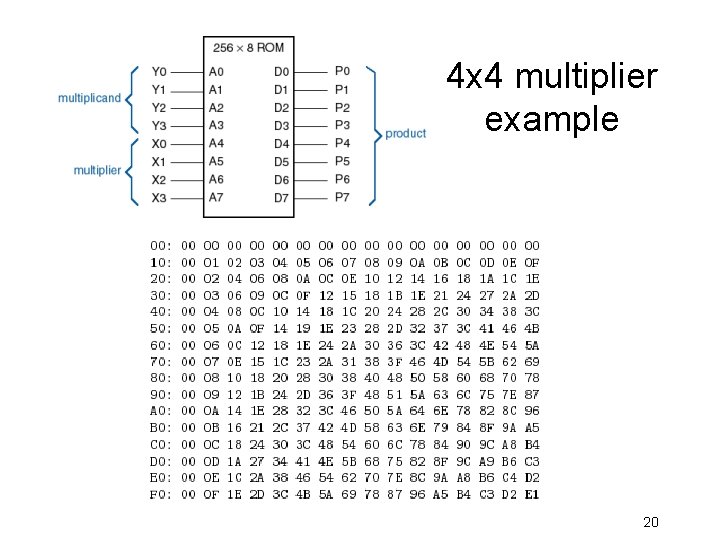
4 x 4 multiplier example 20
Internal ROM structure PDP-11 boot ROM (64 words, 1024 diodes) 21
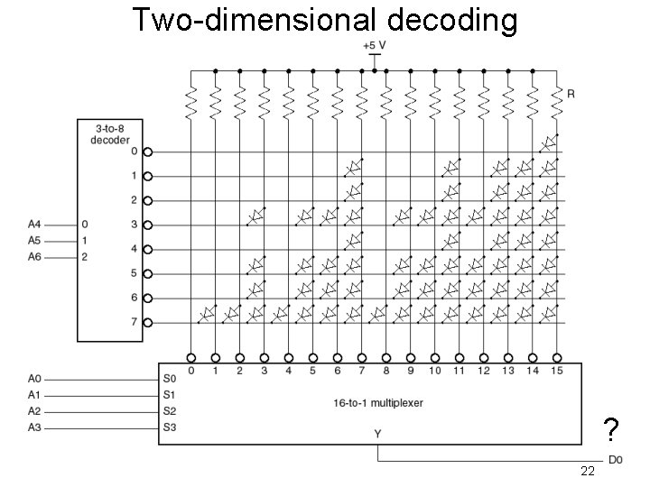
Two-dimensional decoding ? 22
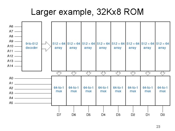
Larger example, 32 Kx 8 ROM 23
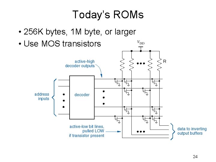
Today’s ROMs • 256 K bytes, 1 M byte, or larger • Use MOS transistors 24
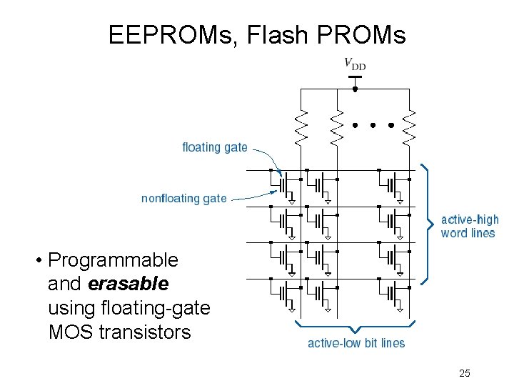
EEPROMs, Flash PROMs • Programmable and erasable using floating-gate MOS transistors 25
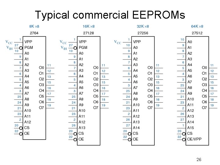
Typical commercial EEPROMs 26
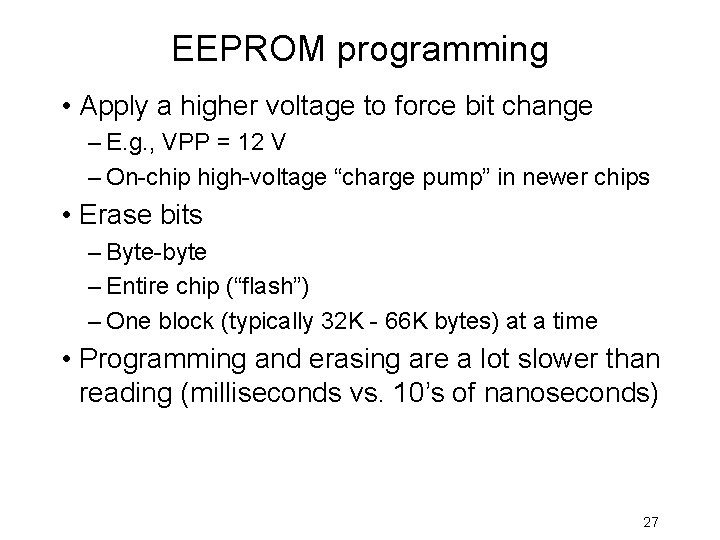
EEPROM programming • Apply a higher voltage to force bit change – E. g. , VPP = 12 V – On-chip high-voltage “charge pump” in newer chips • Erase bits – Byte-byte – Entire chip (“flash”) – One block (typically 32 K - 66 K bytes) at a time • Programming and erasing are a lot slower than reading (milliseconds vs. 10’s of nanoseconds) 27
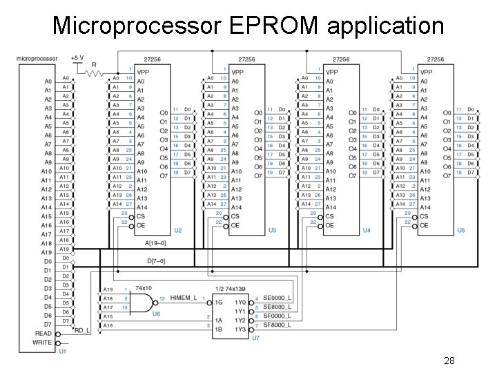
Microprocessor EPROM application 28
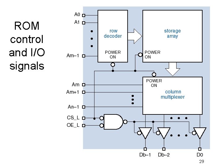
ROM control and I/O signals 29
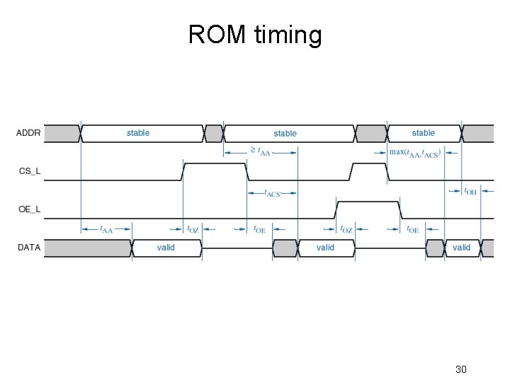
ROM timing 30