Data Movement Instructions A Course in Microprocessor Electrical


 4 The Opcode – The opcode selects the operation (addition, subtraction,")
 – Refer to Fig. 4. 3 for the binary bit pattern")
 4 Register Assignments – Table 3. 3 lists the register assignments")
 4 Special Addressing Mode – It occurs whenever memory data are")
 – The scaled-index byte (R/M=100) is mainly used when two registers")
 4 An Immediate Instruction – suppose the instruction MOV WORD PTR")
 4 Segment MOV Instructions – If the contents of a segment")

 – The PUSHA (push all) instruction copies the registers to the stack")
 – Table 4. 7 lists the forms of the PUSH instruction 4")
 – The POPA (pop all) removes 16 -bit data from the stack")
 4 Initializing the Stack – If the stack area is initialized, load")


 assignments Code W =")
- Slides: 30
Data Movement Instructions A Course in Microprocessor Electrical Engineering Department Universitas 17 Agustus 1945 Jakarta
MOV Revisited 4 The MOV instruction introduces the ma- chine language instructions available with various addressing modes and instructions – It is the native binary code that the microprocessor understands and uses as its instructions to control its operation 4 See the format of the instructions in Fig. 4. 1
MOV Revisited (cont’d) 4 The Opcode – The opcode selects the operation (addition, subtraction, move, etc) performed by the microprocessor – The opcode is either one or two bytes long for most machine language instructions (Fig. 4. 2) • The first six bits of the first byte are the binary opcode • The remaining two bits indicate the direction (D) of the data flow and whether the data are byte or a word (W)
MOV Revisited (cont’d) – Refer to Fig. 4. 3 for the binary bit pattern of the second op-code byte (reg-mod-r/m) 4 MOD field – The MOD field specifies the addressing mode (MOD) or the type of addressing for the selected instruction, and whether the displacement is present with the selected type (Table 4. 1 and 4. 2) – Distinguish the MOV AL, [DI]; MOV AL, [DI+2] and MOV AL, [DI+1000 H]
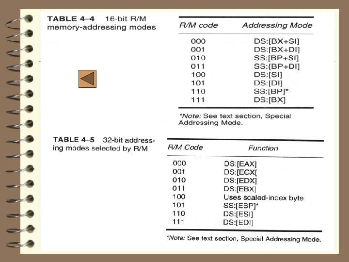
MOV Revisited (cont’d) 4 Register Assignments – Table 3. 3 lists the register assignments for the REG field and the R/M field (MOD=11) – Examine the 8 BECH binary instruction (Fig. 4. 4) 4 R/M Memory Addressing – If the MOD field contains a 00, 01, or 10, the R/M field takes on a new meaning (Table 4. 4) – Figure 4. 5 illustrates the machine language version of the 16 -bit instruction MOV DL, DI or instruction (8 A 15 H)
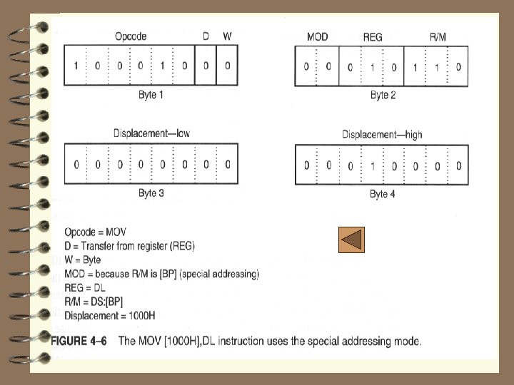
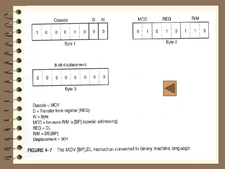
MOV Revisited (cont’d) 4 Special Addressing Mode – It occurs whenever memory data are referenced by only the displacement mode of addressing for 16 -bit instruction s ---> MOV [1000 H], DL – Whenever an instruction has only a displacement, the MOD field is always a 00 and the R/M field is always a 110 (see Fig. 4. 6, Fig. 4. 7) 4 32 -bit Addressing – Table 4. 5. Shows the coding for R/M used to specify the 32 -bit addressing modes
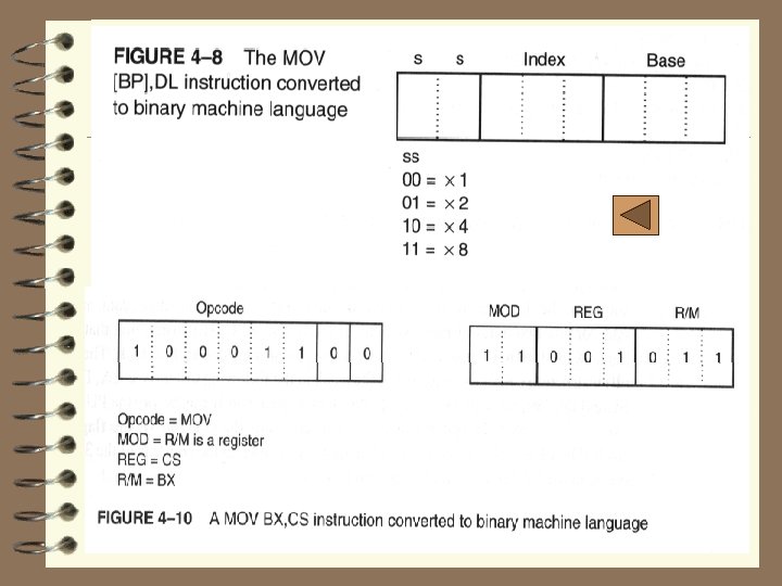
MOV Revisited (cont’d) – The scaled-index byte (R/M=100) is mainly used when two registers are added to specify the memory address in an instruction (Fig. 4. 8)
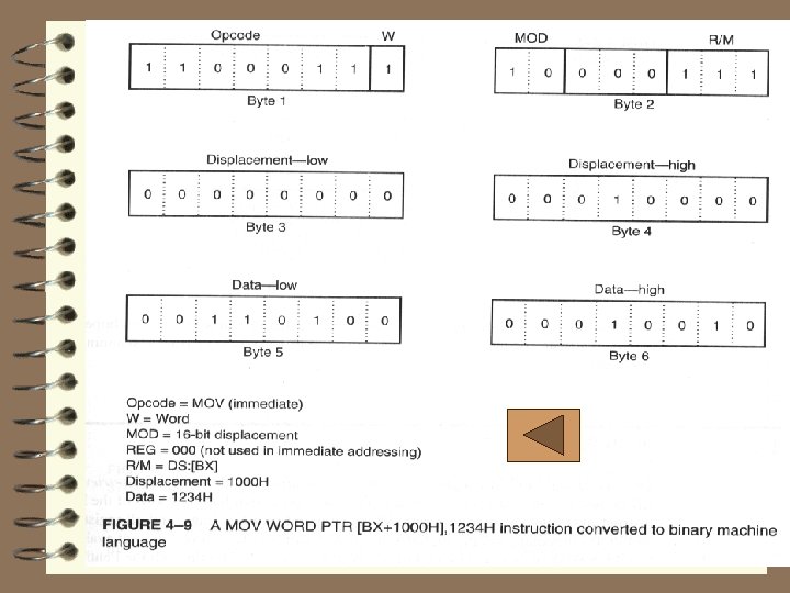
MOV Revisited (cont’d) 4 An Immediate Instruction – suppose the instruction MOV WORD PTR [BX +1000 H], 1234 H that moves 1234 into the word -sized memory location addressed by the sum of 1000 H, BX, and DS x 10 H – The six byte instruction uses two bytes for the op-code, W, MOD, and R/M fields, two other bytes are the data of 1234 H, and the last two are the displacement of 1000 H See Fig. 4. 9
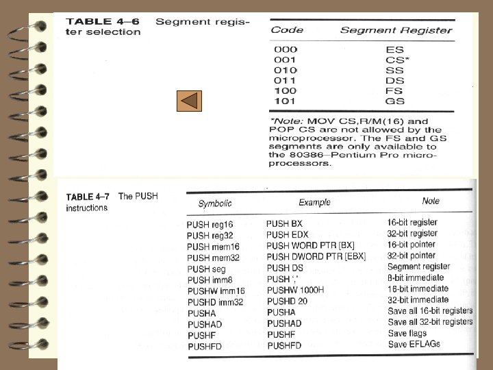
MOV Revisited (cont’d) 4 Segment MOV Instructions – If the contents of a segment register are moved by the MOV, PUSH, or POP instructions, a special set of register bits (REG field) selects the segment register (see Table. 4. 6) – Figure 4. 10 shows a MOV BX, CS instruction converted to binary – The op-code is different for the prior MOV – Segment registers can be moved between any 16 -bit memory location or 16 -bit memory location
PUSH/POP 4 These are important instructions that store and retrieve data from the LIFO stack memory • There are six forms of the PUSH and POP instructions: register, memory, immediate, segment register, flags, and all registers 4 PUSH – It transfer two or four bytes of data to the stack – PUSHA instruction copies the contents of the internal register set, except the segment registers to the stack
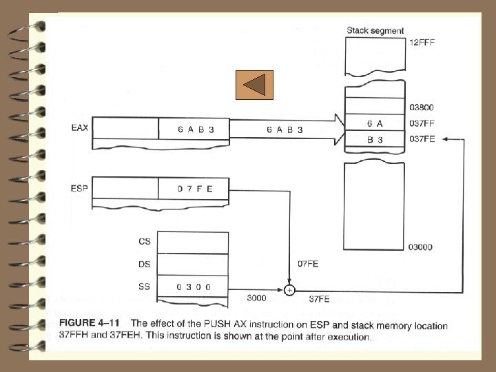
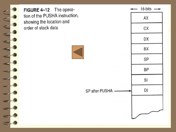
PUSH/POP (cont’d) – The PUSHA (push all) instruction copies the registers to the stack in the following order: AX, BX, CX, DX, BX, SP, BP, SI, and DI – The PUSHF (push flags) instruction copies the content of the flag register to the flack – Figure 4. 11 shows the operation of the PUSH AX • AX --> SS: [SP-1] = AH, SS: [SP-2] = AL, and afterward SP = SP - 2 – Figure 4. 12 illustrates the result of the PUSHA instruction
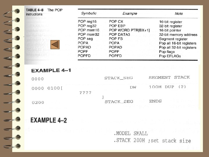
PUSH/POP (cont’d) – Table 4. 7 lists the forms of the PUSH instruction 4 POP – It performs the inverse operation of PUSH, i. e. , removes data from the stack and places it into the target 16 -bit register, or a 16 -bit memory location – POPF (pop flags) removes 16 -bit number from the stack and places it into the flag register – The POPFD removes 32 -bit number from the stack & places it into the extended flag register
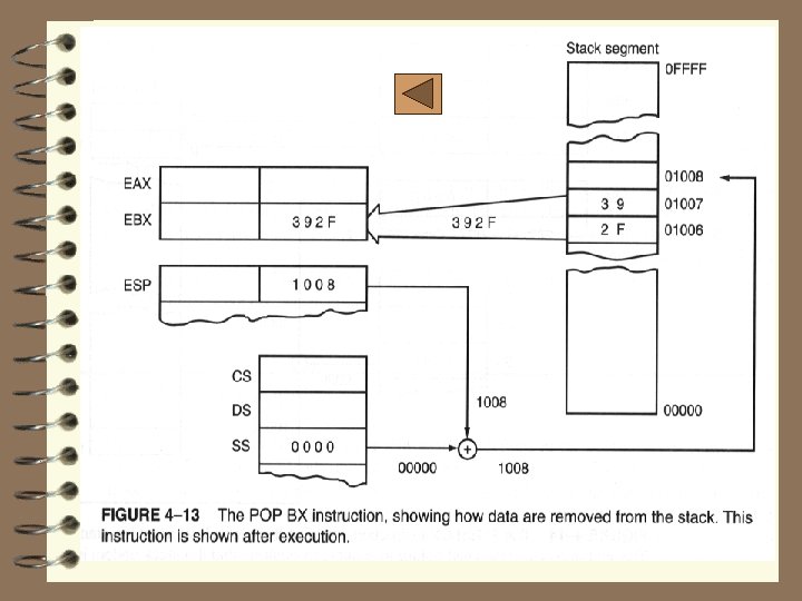
PUSH/POP (cont’d) – The POPA (pop all) removes 16 -bit data from the stack and places it into the following registers in order: DI, SI, BP, SP, BX, DX, CX, and AX; this is a reverse order from the way they are placed on the stack by the PUSHA – Figure 4. 13 shows how the POP BX removes data from stack into BX – Table 4. 8 lists the op-codes used for the POP and all of its variations
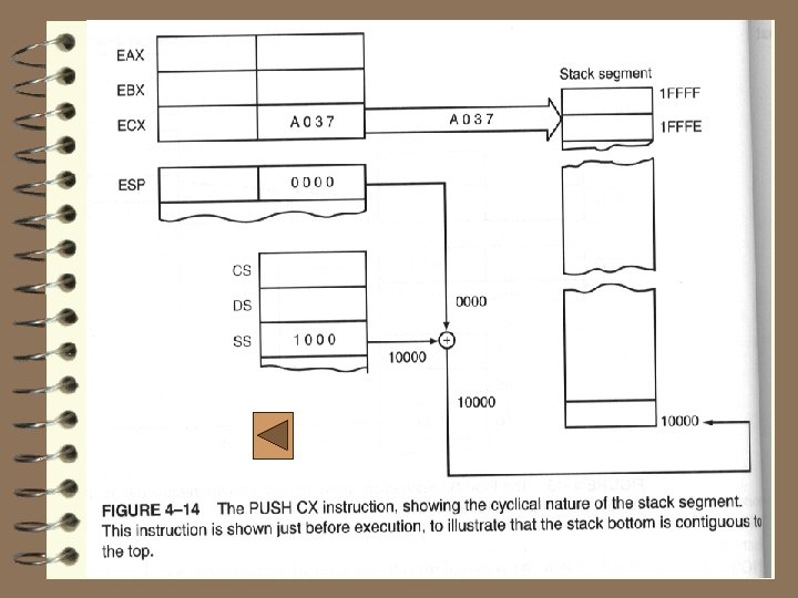
PUSH/POP (cont’d) 4 Initializing the Stack – If the stack area is initialized, load both the SS and SP registers; SS is normally designated with the bottom location of the stack segment – Fig. 4. 14 shows how the beginning of stack segment is formed and used in PUSH CX – A stack segment is set up as illustrated in example 4. 1 and example 4. 2
16 -bit instruction mode Opcode MOD-REG-R/M Displacement Immediate 1 -2 bytes 0 -1 bytes (a) 32 -bit instruction mode (80386 through Pentium 4 only) Address size Register size Opcode MOD-REG-R/M Scaled-index Displacement Immediate 0 -1 bytes 1 -2 bytes 0 -1 bytes (b) Figure 4 -1 The formats of the 8086 -Pentium 4 instructors. (a) The 16 -bit form and (b) the 32 -bit form.
D W Opcode Figure 4 -2 Byte 1 of many machine language instructions, showing the position of the D- and W-bits. MOD REG R/M Figure 4 -3 Byte 2 of many machine language instructions, showing the position of the MOD, REG and R/M fields.
Opcode 1 0 0 0 1 0 D W MOD 1 1 REG 1 0 R/M 1 1 0 0 Opcode = MOV D = Transfer to register (REG) W = Word MOD = R/M is a register REG = BP R/M = SP FIGURE 4 -4 The 8 BEC instruction placed into bytes 1 and 2 formats from Figures 4 -2 and 4 -3. This instruction is a MOV BP, SP Opcode 1 0 0 0 1 0 D W MOD 1 0 0 0 REG 0 1 R/M 0 Opcode = MOV D = Transfer to register (REG) W = Byte MOD = No displacement REG = DL R/M = DS: [DI] FIGURE 4 -5 A MOV DL, [DI] instruction converted to its machine language form. 1 0 1
TABLE 4 -1 MOD field for the 16 -bit instruction mode TABLE 4 -2 MOD field for the 32 -bit instruction mode (80386 -Pentium 4 only) MOD Function 00 No displacement 01 8 -bit sign-extended displacement 10 16 -bit signed displacement 11 R/M is a register MOD Function 00 No displacement 01 8 -bit sign-extended displacement 10 32 -bit signed displacement 11 R/M is a register
TABLE 4 -3 REG and R/M (when MOD = 11) assignments Code W = 0 (Byte) W = 1 (Word) W = 1 ( Doubleword) 000 AL AX EAX 001 CL CX EAX 010 DL DX EDX 011 BL BX EBX 100 AH SP ESP 101 CH BP EBP 110 DH SI ESI 111 BH DI EDI