Course code EEE4123 High Voltage Engineering Lecture11 12


 w. r. to x and inserting equn")


. The corresponding")


 The voltage wave of magnitude 100 k. V which is initiated in an")


- Slides: 35
Course code : EEE-4123 High Voltage Engineering Lecture-11, 12, 13 Topics High voltage Transient analysis: Source: High Voltage Engineering by JR Lucas Chapter 4 Presented by Md. Shamim Sarker Assistant professor Dept. of EEE, KUET
Surges on Transmission Lines The voltage drop across PQ and the corresponding current through it are given by the following equations.
Eliminating dx we get Diff. equn (1) w. r. to x and inserting equn (2) in that equation, we get
A very similar partial differential equation can be obtained for i. In practical power lines, the resistance r is much less than the inductance l, and the conductance g is negligible.
A very similar partial differential equation can be obtained for i. In practical power lines, the resistance r is much less than the inductance l, and the conductance g is negligible.
Thus the general solution of this partial differential equation is where f and F are two arbitrary functions of (x-at) and (x+at). These two functions can be shown to be forward and reverse traveling, as follows.
Surge Impedance of travelling wave Consider the forward wave e = f(x-at). The corresponding current wave i ,
Velocity of propagation of Travelling wave For a transmission line, with conductors of radius r and conductor spacing d, it can be shown that the inductance per unit length of the line (neglecting internal flux) is given by The capacitance c per unit length is given by
Therefore the velocity of propagation of the wave a is equal to the velocity of light. [Note: If the resistance of the line was not neglected, the velocity of propagation of the wave would be found to be slightly less than that of light (about 5 to 10%)]. For a cable, the dielectric material has a relative permittivity r different from unity. In this case, the above derivation would give the velocity of propagation in a cable as
Energy Stored in Surge The energy stored in a traveling wave is the sum of the energies stored in the voltage wave and in the current wave. We know, Squiring, OR, It is seen that half the energy of the surge is stored in the electrostatic field and half in the electromagnetic field.
Reflection of Traveling waves at a Junction For Voltage and current continuity at junction
If the line is open at far end then Z 2 is Zero and then If the line is open at far end then Z 2 is infinity and then
Open circuited line fed from a infinite source When a voltage surge E arrives at the junction J, which is on open circuit, it is reflected without a change in sign (i. e. E) Also, a current surge (- I) of opposite sign to the incident (I) is reflected so that the transmitted current is zero If the line is fed from a constant voltage source E, then as the reflected voltage surge (E) arrives at the generator end, since the generator maintains the voltage at its end at voltage E, it send a voltage surge
The voltage surge - E is accompanied by a current surge - I. The surge voltage - E as it reaches the open junction J, is reflected again without a change in sign, and accompanied by a current + I so as to make the transmitted current again zero. Once these voltage and current waves reach the generator, the instantaneous voltage & current will be zero, and the line would once again be uncharged. The generator now sends a voltage surge E accompanied by a current surge I, and the who process described repeats again
Short Circuit Line fed from an infinite source When a voltage surge E arrives at the junction J, which is on short circuit, it is reflected with a change in sign (- E), so as to cancel the incoming surge. Also, a current surge I of the same sign as the incident (I) is reflected so that the transmitted current is doubled (2 I). If the line is fed from a constant voltage source E, then as the reflected voltage surge (- E) arrives at the generator end, it send a voltage surge of E back to the line so as to keep its voltage at E
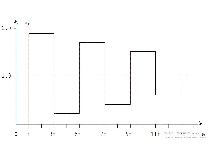
Bewley Lattice Diagram This is a convenient diagram devised by Bewley, which shows at a glance the position and direction of motion of every incident, reflected, and transmitted wave on the system at every instant of time. When a voltage surge of magnitude unity reaches a junction between two sections with surge impedances Z 1 and Z 2, then a part a is transmitted and a part B is reflected back. In traversing the second line, if the attenuation factor is k, then on reaching the termination at the end of the second line its amplitude would be reduced to k. a
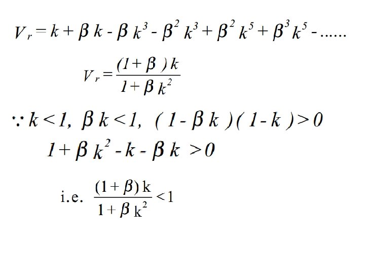
Analysis of an open-circuit line fed from ideal source Thus the voltage at the open end after the n-th reflection is given by
This is a geometric series which has the summation given by
For line terminated through a resistance R
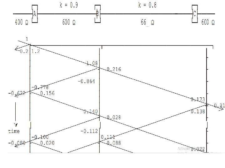
Reflections at 3 substation system 1 2 3
For Station A: For Station B:
k=0. 9 k=0. 8
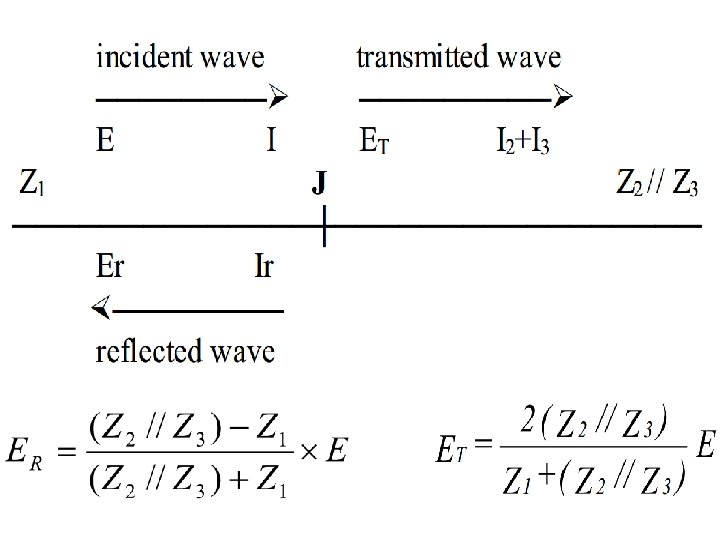
Reflection and Transmission at a T-junction and
Reflection and Transmission at a T-junction
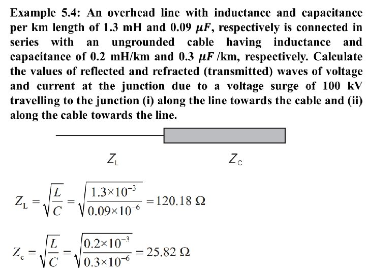
Example 5. 1: A cable has a conductor of radius 0. 75 cm and a sheath of inner radius 2. 5 cm. Find (i) the inductance per meter length (ii) capacitance per meter length (iii) surge impedance and (iv) velocity of propagation, if the permittivity of insulation is 4. Radius of conductor, r = 0. 75 cm (iii) Surge impedance Inner radius of sheath, R = 2. 5 cm Permittivity of insulation, ε r = 4 (i) inductance (ii) Capacitance (iv) Velocity of Wave propagation
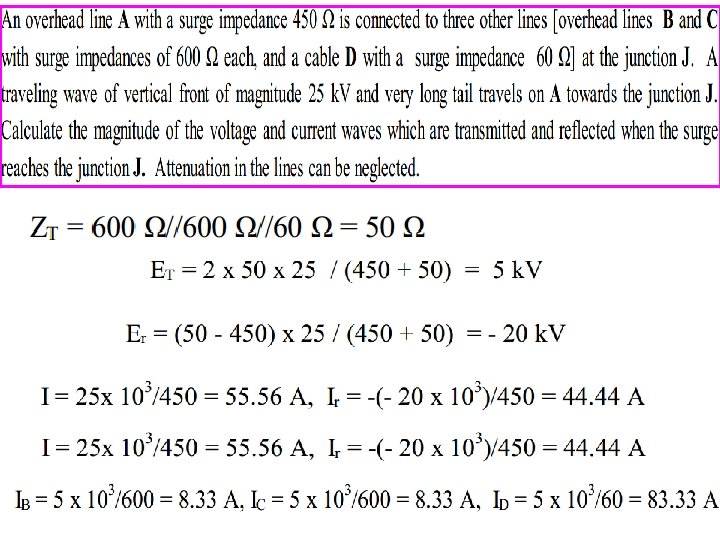
(i) The voltage wave of magnitude 100 k. V which is initiated in an overhead line: Do Yourself
The ends of two long transmission lines, A and C are connected by a cable B of length 1 km. The surge impedances of A, B and C are 400, 50 and 500 Ω, respectively. A rectangular voltage wave of 25 k. V magnitude and of infinite length is initiated in A and travels to C. Determine the first and second voltages impressed on C.
Second impressed voltage =v 4 + v 6= 10. 11 + 6. 44=16. 55 k. V