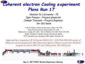
Coherent electron Cooling Proof of Principles Vladimir N


- Slides: 39

Coherent electron Cooling Proof of Principles Vladimir N. Litvinenko for Ce. C team C-AD, Brookhaven National Laboratory, Upton, NY, USA Stony Brook University, Stony Brook, NY, USA Niowave Inc. , Lansing, MI, USA Tech X, Boulder, CO, USA Budker Institute of Nuclear Physics, Novosibirsk, Russia STFC, Daresbury Lab, Daresbury, Warrington, Cheshire, UK Supported by BNL (LDRDs & PD), C-AD AR&DD, and NP Do. E office Accelerator R&D grant

Ce. C is novel and untested technique & clearly requires proof-of-principle facility Goals of Ce. C Po. P system Demonstrate energy cooling with Ce. C Compare with theory and simulations Cool entire beam – then Use for advanced Ce. C Use for linac-ring beam-beam effects studies 2

Dec. 4 -5, 2012, External Review Oliver Brüning (Chair), Valeri Lebedev, Robert Palmer, Hasam Padamsee, Executive Summary Coherent Electron Cooling (Ce. C) is a very appealing fundamentally new concept that could offer an impressive increase in cooling power for high energy bunched hadron beams (e. g. three orders of magnitude wrt stochastic cooling in RHIC). The Ce. C Po. P is a major component of the R&D for a high luminosity Electron-Ion Collider at BNL (e. RHIC). Next Do. E Review: Nov. 12 -13, 2015 3

Ce. C Proof-of-Principle Experiment Coherent electron Cooling Po. P

Our Po. P is based on an economic version of Ce. C: it limits strength of the wiggler aw to about 0. 5 but it is very cost effective Param. ’s from 40 Ge. V proof-of-principle exp. at BNL Bunching computed from charge density perturbation & entered into GENESIS FEL simulation. VORPAL 3 D δf PIC computation of e- density perturbation near Au+79 ion (green) vs. idealized theory (blue). On Cray XE 6 cluster at NERSC. GENESIS output converted into VORPAL-compatible input. GENESIS parallel computation of electron beam bunching in free electron laser (FEL) shows amplification of modulator signal. VORPAL prediction of the coherent kicker electric field E k due to e-density perturbation from modulator, amplified in the FEL. Simulations by Tech-X 5

Electron Beam and FEL Parameters Electron Beam RMS Energy Spread ≤ 1× 10 -3 Normalized Emittance Peak Current FEL Wiggler Length ≤ 5 μm. rad 60 -100 A Wiggler Period Wiggler Strength, aw FEL Wavelength 40 mm 0. 5 +0. 05/-0. 1 13. 6 μm 3× 2. 5 m

Main Beam Parameters for Ce. C Experiment Parameter Species in RHIC Relativistic factor Number of particles in bucket Value Au+79 ions, 40 Ge. V/u 42. 96 109 Electron energy Charge per e-bunch Rep-rate Average e-beam current Electron beam power 21. 95 Me. V 0. 5 -5 n. C 78. 17 k. Hz 0. 39 m. A 8. 6 k. W

Expected Electron Beam Parameters Calculations are done for 2 n. C bunch Core charge is 1. 3 n. C Emittance is 8. 6 μm, core emittance is 3. 3 μm Relative energy spread is 2× 10 -3, relative energy spread in the core is 3× 10 -4 Courtesy D. Kayran

Ce. C Po. P RHIC Ramp Development Ramp : beam intensity Ramp : Magnets currents Emittance growth at 40 Ge. V APEX on RUN 11: 2 pm-4 pm, June 20 th , 2011 Fill: 16093 Bunch length and profiles at 40 Ge. V

Ion Beam Parameters Characterization Orbit motion below 200 microns peak-to-peak. Beam RMS size is ~500 um R. m. s. jitter is better than 50 ps Noise floor is 80 d. B below the signal at revolution frequency.

Matching velocities/relativistic factors We rely on the increase of the shot noise in electron beam which is induced by ion’s in the modulator Simulations parameters Electron beam: peak current 70 A 79 Au 197 beam: peak current 3. 37 A

Anticipated Beam Dynamics Electron bunch – 10 psec Ion bunch – 2 nsec Well above noise floor r. m. s. length of the cooled part 80 -120 ps. The cooling effects can 2 GHz (or more) bandwidth using spectrum analyzer or digital scope Simulated beam profile evolution with Ce. C Po. P parameters

Cooling full bunch Self-consistent simulations Preliminary © G. Wang Plot shows evolution of Au ion bunch profile after 40 mins of Ce. C using 1 n. C (10 psec long) and 3 n. C (30 psec long) electron bunches.

Location – RHIC 02: 00 Region 14 Coherent electron Cooling Po. P

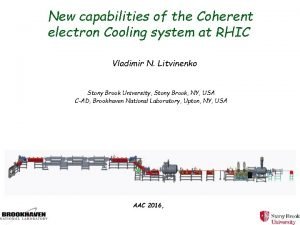
Ce. C Po. P Final Configuration Beam Line in RHIC IP Utility Building Water/Cryogenics Service Building Diagnostics Laser Room (New) Service Building Vacuum Coherent electron Cooling Po. P PS Building RF and Magnets

Phase 1 – Beamline installation and 112 MHz Cavity Testing Ce. C Phase 1 goals: • Install 112 MHz Cavity, Support Systems, and Cathode • Install Beamline and Low Intensity Dump • Make 112 MHz Cavity Cold and Test (October 20)“dry run”, ASSRC walk through (October 27) cold test (October 30) conditioning underway (December 4) 2 MV !! Coherent electron Cooling Po. P

Phase 2. 1: Buncher to Dump Beamline Coherent electron Cooling Po. P

Ce. C Po. P @ IP 2 Coherent electron Cooling Po. P

Infrastructure Coherent electron Cooling Po. P

Phase 1 conditioning 112 MHz Cavity Coherent electron Cooling Po. P

Results of our success with 112 MHz gun 1. 6 -1. 7 Me. V (kinetic energy) e-Beam with 3 n. C in CW mode 2 Me. V in pulse mode 25 MV/m at phtocathode Milestones Q 3 FY 15 Demonstrating operation of 112 MHz SRF gun with 3 n. C charge per bunch, 1. 6 to 1. 7 Me. V kinetic energy in CW mode and above 2 Me. V in pulsed mode. Production of high QE photocathodes for 112 MHz SRF gun. Receiving helical wiggler system for Ce. C Po. P FEL amplifier Completion of the 704 MHz SRF linac cryo-module at Nio. Wave Inc. Completing the low energy transport beam line and its control system.

Phase 3: Full Energy Beam Line Installation - 2015 • • • Install 704 MHz Systems and supporting cryogenic system Install Wiggler Magnets Install RHIC beam line components: dipoles, quads, correctors, vacuum Install beam diagnostics (Toby) Modify and install RHIC DX-DO chamber for FEL light diagnostics Move Ce. C beam dump line to final location

Phase 3 - 704 MHz 5 Cell Cavity From Niowave Delivery from Niowave – July 15, 2015 Coax in house being installed FPC welding at AES is finished Coherent electron Cooling Po. P

Wigglers at BNL BINP team just left

Phase 3 - 704 MHz Cryogenics • Integration with LERe. C supply and return requirements complete • All components ordered: VJP (green monster), heater return (blue), cooldown return (lime green to QHS heater), heater skid. • Warm return vacuum header installation • 704 MHz scaffold order Coherent electron Cooling Po. P

We are on the move with Ce. C Po. P

More pictures

Resources needed for 2 years Funding for hardware – $1. 2 M Personnel – an estimate is about 20 men-years (to be determined when resource loaded schedule is finalized) People involved: VL, I. Pinayev J. Tuozzolo, J. Skaritka, Y. Hao, Y. Jing, G. Wang, D. Kayran, B. Xiao, B. Sheehy, E. Wang, T. Rao, Z. Altinbas, S. A. Belomestnykh, K. A. Brown, J. C. Brutus, A. J. Curcio, L. De. Santo, C. Folz, D. M. Gassner, C. Ho, R. L. Hulsart, M. Ilardo, J. P. Jamilkowski, F. X. Karl, N. Laloudakis, R. F. Lambiase, G. J. Mahler, M. Mapes, W. Meng, R. J. Michnoff, T. A. Miller, M. G. Minty, G. Nayara, P. Orfin, F. Randazzo, , J. Sandberg, K. S. Smith, L. Snydstrup, A. N. Steszyn, R. Than, C. Theisen, R. J. Todd, D. Weiss, M. Wilinski, A. Zaltsman. R. Kellerman, T. Xin, D. Ravikumar, Y. Wu (definitely missed somebody!)

Summary • • • Progress continues on component installation and commissioning. 112 MHz generated electron beam during RHIC run 15 Critical deliveries: 704 MHz cavity and undulator magnets had been made Installation summer 2015 Main uncertainty is introduced by potential p-A operation during Run 16 Coherent electron Cooling Po. P

Schedule Construction Ce. C Po. P experiment is a DOE NP competitive R&D project – we are submitting quarterly progress and budget reports x - a milestone, X – major milestone Delivery of 704 MHz linac to BNL Assembling and tuning helical wigglers Installing/plumbing the 704 MHz in RHIC tunnel Install helical wigglers in RHIC tunnel CW laser is commissioned Beam diagnostics is intalled Optical diagnostics is installed Complete Ce. C beam-line ✓ 2/3 done x x x X 30 -Jul-15 1 -Oct-15 15 -Nov-15 01 -Dec-15 15 -Dec-15

Ce. C experiment is now a part of RHIC Run-16 plan

Schedule for RHIC run 16 (dates are tentative and are adjusted to the preliminary RHIC Run 16 schedule) Commissioning Milestones End date SRF cavities cold x 15 -Jan-16 Has to be synchronized with RHIC run Complete cavity conditioning X 20 -Feb-16 Generating first beam X 10 -Mar-16 Measuring beam parameters X 1 -Apr-16 Propagate beam to the beam dump x 20 -April-16 Test co-propagation with ion beam X 1 -May-16 Demonstrate FEL amplification X 15 -May-16 First cooling attempt X 02 -Jun-16 Dedicated 5 days of running

Schedule - demonstration (dates are tentative and will be adjusted to RHIC Run 17) Making necessary upgrades/improvements SRF cavities cold Complete cavity conditioning Recreating operational conditions Start Ce. C Po. P experiments (using APEX shifts) Demonstrate microbunching amplification (ACe. C) Demonstrate Ce. C Po. P cooling Ce. C cooling experiments end Improving and updating diagnostics, optical system, as well as installing buncher for 01 -Jul-16 31 -Dec-16 ACe. C test x 15 -Feb-17 Has to be synchronized with RHIC run X 01 -Mar-17 X 21 -Mar-17 X 07 -Apr-17 x X 30 -May-17 if time allows 30 -Jun-17 Dates have to be adjusted to the end of the 30 -Jun-17 RHIC run X

Ce. C Po. P Where scientists and engineers work together ! Coherent electron Cooling Po. P

BACK-UP

Cathode Deposition and Transfer Modify cathode deposition system to avoid coverage of the cathode sides with photoemissive material “Serial” production of the cathodes for operation Photocathode end assembly

FEL amplifier simulation II: With shot noise from electrons: γ=21. 8 Peak current: 100 A Norm emittance 5 mm mrad RMS energy spread 1 e-3 λw=4 cm aw = 0. 4 λo=12. 7 um Mc = 35. 8 ©Y. Jing 3 D Genesis simulation shows that the maximal gain in bunching factor is 409, which agrees with our estimation. 37

Field Reduction due to Finite Transverse Modulation Size © V. N. Litvinenko

Simulation of ion beam I: Ion beam profile evolution in 10 seconds (preliminary) Electron bunch charge: 3 n. C Electron bunch length: 30 ps Ion bunch intensity: 1. 6 E 8 Ion bunch length: 3. 5 ns Ion energy spread (RMS): 3. 8 E-4 Ce. C gain: 100 (Ep=50 V/m)
 Direct proof and indirect proof
 Direct proof and indirect proof
 Write an indirect proof
 Direct proof and indirect proof
 Algebraic proof
 Algebraic proof definition
 Coherent and incoherent sources of light
 Coherent text
 Cohesive presentation
 Photodesintegration
 Lexical cohesion examples
 Coherent thought
 Coherent detection in optical communication
 Scattering of light definition
 Coherent and cohesion meaning
 Coherent scattering
 Coherent accelerator processor interface
 Mti radar vs pulse doppler radar
 Coherent line drawing
 Probability of error for non coherent fsk
 Modulating index
 Putting principles into practice
 Evolutionary software process models
 Coherent sampling
 Rangkaian coherent detector am-dsb-sc terdiri dari
 Importance of coherent lesson plan
 Paragraph example
 Writing a coherent review of literature
 Example of coherence
 Coherent ui a modern user interface
 Designing coherent instruction artifacts
 Coherent
 Pulsed coherent radar
 David eber cmu
 Case of the cooling corpse answer
 Definition of vocabulary
 Heat load calculation software
 R22 temp chart
 Electronic cooling methods
 Ysfc
Ysfc
