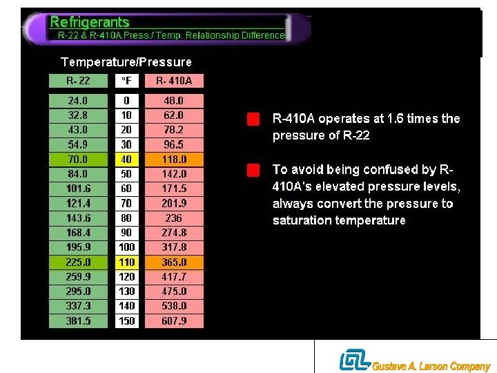
Refrigerant R410 A R22 This is your programtime


 Condenser Evaporator Suction")


 #2 -Suction Vapor Density: 1. This is the weight of the refrigerant")
 The refrigerant in low pressure side of refrigeration")


 1. The Trane Company found R-410 A to be one of")
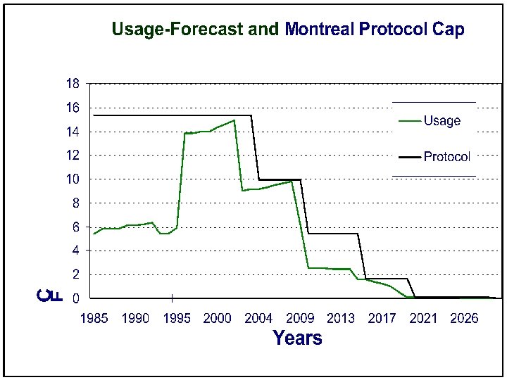
 Phaseout in U. S.")


 for R-410 A is 0. 00")


 • Store at 125 degrees or")


")


, and the liquid line")


- Slides: 136
Refrigerant R-410 A & R-22
This is your program/time: ask questions, use your time wisely…it’s not the cost of the program (money wise), but your time spent here that is important…dollar wise, this is cheap, however you /me only have 24 hours/day in that respect we are all equal…but it’s how you spend that time that is important….
Questions? /Comments! Feel free at any time to ask questions, or to make a comment. There are NO dumb questions…. only the answers!!! And the instructors are responsible for those. This is your meeting, enjoy and participate……. .
Service Advisors Gustave A. Larson Company Plymouth Office: 800 -827 -9508 763 -546 -9508 Gale Patterson ext. 343 Steve Le. May ext. 346 Pewaukee Office: 800 -829 -9609 Steve Bukosky ext. 247 Larry Lemens ext. 285
Thermodynamics Saturation Temperature Density of Refrigerant Vapor Enthalpy Superheated Vapor Subcooled Liquid
Heat Transfer Hot Object Cold Object HEAT
Latent and Sensible Heat
Basic Refrigeration Condenser Thermostatic Expansion Valve Compressor Evaporator
Refrigerant Piping Liquid Line Thermostatic Expansion Valve Discharge Line ¡(High Side) Condenser Evaporator Suction Line ¡(Low Compressor Side)
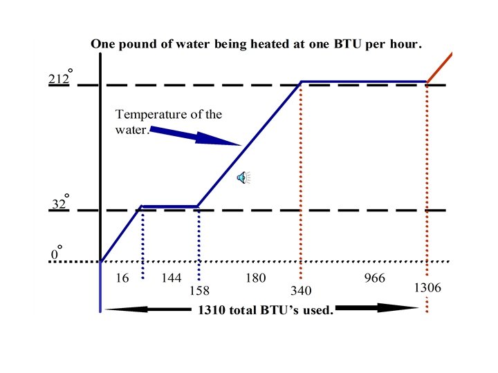
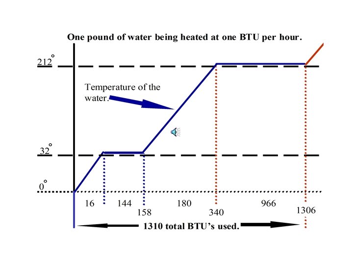
What does Saturation Temperature Mean? 1. Saturation Temperature is the actual temperature of the evaporator and condenser coils. 2. In saturation conditions vapor & liquid are present.
Saturation Temperature How Do You Find Saturation Temperature? Refrigeration Gauges >The Only Purpose of Owning a Set of Refrigeration Gauges Is to Find the Refrigerant Saturation Temperature.
Saturated Refrigerant Saturated Refrigeration i Liquid and Vapor in Contact with Each Other in Equilibrium i Pressure and Temperature Tied Together i P/T Chart is Applicable Example: Conditions, R-22 - 287 PSIG 128°F Temperature P-T Chart at 287 PSIG R-22 = 128°F Line Temperature = Refrigerant is Saturated 128°F
Pressure/Temperature Chart
Saturated Refrigerant Liquid Line Thermostatic Discharge Line Expansion Valve Condenser Evaporator Suction Line Compressor
Sensible And Latent Heat Transfer In the Evaporator Coil 1. Latent Heat Transfer: -Greatest ability to absorb heat -Causes change of state -Refrigerant remains saturated 2. Compressors cannot pump liquid 3. Sensible Heat Transfer: -Heat added to refrigerant/no change in state - Superheated condition
Latent and Sensible Heat Transfer in the Evaporator Coil A B C D E
Thermodynamics/Evaporator #1 -Saturation Temperature: 1. If any heat is added or removed to the temperature, at a given pressure a change of state occurs. 2. At saturation temperature, both liquid and vapor are present. 3. The saturation temperature is the temperature of the evaporator coil.
Thermodynamics/Evaporator (con’t) #2 -Suction Vapor Density: 1. This is the weight of the refrigerant vapor, in Pounds per Cubic Foot Of Vapor. 2. Suction Vapor Density causes the compressor to vary in amperage draw. 3. Suction Vapor Density causes the system’s pressures to rise and fall.
Thermodynamics And The Evaporator Cycle (Summary) The refrigerant in low pressure side of refrigeration cycle goes through three (3) changes: 1. Saturation Temperature 2. Suction Vapor Density 3. Superheating of Suction Vapor
Thermodynamics/Evaporator -Superheating Of Suction Vapor: 1. Superheat is the temperature of the vapor above its saturation temperature. 2. Superheat is done by the load. 3. Superheating is a Sensible Heat Transfer providing very little cooling effect.
Superheating i. Heat Added to Refrigerant Vapor that Causes its Temperature to Rise Above its Saturation Temperatures i. P/T Charts Do Not Apply Temperature Rises Without a Rise in Pressure Superheated Refrigerant Example: Conditions, R-22 - 75. 0 PSIG Suction Line - 54°F Line Temperature = 54°F P-T Chart at 75. 0 PSIG = 44°F 10°F Coil Operating at 10°F Superheat
Superheated Refrigerant Liquid Line Thermostatic Discharge Line Expansion Valve Condenser Evaporator Suction Line Compressor
Sub-Cooling i Heat Removed from the Liquid Refrigerant that Causes its Temperature to Drop Below its Saturation Temperature i P/T Charts do not Apply- Temperature Drops without a Drop in Pressure Example: Conditions, R-22 - 280 PSIG 120°F Line Temperature P-T Chart at 280 PSIG = 125°F Line Temperature 120°F 5°F Refrigerant Sub-cooled at 5°F =
Thermodynamics/Condenser Coil -Purpose of condenser coil is to reject the heat load absorbed by evaporator coil, and to cool the refrigerant to a level that is below the saturation temperature. -This is accomplished through (1) Latent Heat Transfer, and (2) Sensible Ht. Transfer. -Proper sub-cooling prevents saturated refrigerant from leaving the condenser, thus optimizing metering device performance.
Sub-Cooled Liquid -Typical subcooling levels - 5 to 20 degrees -Not enough subcooling, or large pressure losses in the liquid line create the formation of flash gas will affect the operation of the metering device. -10 degrees overcomes 35 PSIG of liquid line pressure drop in R-22 systems. -10 degrees overcomes 50 PSIG of liquid line pressure drop in R-410 A systems.
Sub-Cooled Liquid Line Thermostatic Discharge Line Expansion Valve Condenser Evaporator Suction Line Compressor
Three Conditions of the Refrigerants Liquid Line Thermostatic Discharge Line Expansion Valve Condenser Evaporator Suction Line Compressor
Another New Refrigerant *In 1987 the world approved the Montreal Protocol and the United States wrote it in to law. *The law states that refrigerant R-22 can not be used in the manufacturing of new equipment after 2010. *In the mid 80 s Trane began testing alternate refrigerants.
A New Refrigerant(con’t) 1. The Trane Company found R-410 A to be one of the best alternate refrigerants available. 2. When it became apparent that R 410 A would be the next main stream refrigerant, Trane began national field testing (prior to 96, field testing had only been done on a limited basis).
Projected U. S. Refrigerant Demand HCFC (R-22) Phaseout in U. S.
What about R-22? ¿ R-22 can be produced until 2020 for the service of installed systems. ¿ Reclaimed R-22 may be available forever! ¿ R-22 is not expected to see the drastic price increases as R-12 did, most the result of taxes.
What is R-410 A? <R-410 A is a blend of two refrigerants, near Azeotropic mixture of 50% HFC-32 and 50% HFC-125. <Many of us have been using refrigerant blends for awhile, R-502. <The Temp. Glide is negligible (< 0. 3°F). <There is no significant change in composition due to system leaks.
What is R-410 A? +The Ozone depletion potential(ODP) for R-410 A is 0. 00 Vs 0. 05 for R-22 (1. 0 is R-12 which is the baseline established by EPA). +The ASHRAE safety classification is A 1/A 1, the same as R-22. +Boiling point is -62. 9°F Vs -41. 4°F for R-22.
WHAT IS A 1/A 1 • A rating is an indication of no toxicity at concentrations of less than 400 ppm. • 1 is a flammability classification that indicates no flame propagation. • There are two ratings because R 410 A is a blend of different two refrigerants.
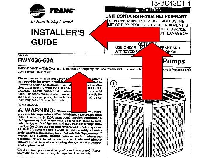
WHAT IS R-410 A? ? Thermal stability is similar to R-22. ? Handling cautions are the same as R-22. ? Remember 50 to 70% higher pressures require the proper tools for servicing.
R-410 A … POE Oil • Oil is different than R-22 – polyolester rather than mineral oil. . POE • POE is hygroscopic. It absorbs moisture rapidly. – Liquid line driers must be changed when the system has been open. A good vacuum will not get all the water out.
POE Oils ENon-contaminated POE oils will not harm skin. E Non-contaminated POE oil has a light sweet odor. EPOE’s are classified as nonhazardous.
POE Oils EPOE oils from a severe acid system will smell like dirty diapers. ESevere burn outs create acids and alcohol and moisture. E Waste oil may be disposed through waste recyclers.
POE Oils-WARNING ? Synthetic oil will attack many roofing materials. When servicing equipment mounted on a roof, the roof must be protected from oil spray or spills. Use a plastic covering or tarp to protect the work area. ? Wiping up a spill will not stop long term damage to the roofing materials.
Special Considerations For POE Oils * System contains POE oils that absorb moisture faster than current mineral oil. * Unopened containers have less than 50 ppm/ water.
POE Oils ‡ Open containers can absorb 1500 to 2000 ppm/ water. ‡ Keep containers sealed when not in use. ‡ Use reasonable refrigeration practices.
Moisture, POE Oil, and Driers MOISTURE IS BAD - DRIERS MUST BE REPLACED EVERY TIME A REFRIGERANT COMPONENT IS REPLACED OR THE SYSTEM IS OPENED FOR SERVICE
Special Considerations Moisture òVacuum pumps will not completely remove moisture, driers must be replaced every time a refrigerant component is replaced. òNot even a deep vacuum will remove moisture from POE oils!
PPM Moisture Oil Moisture Absorption Rate Time Minutes
Discus Compressors/Polyol Ester Oil Moisture Content Versus Time Sample Size: 13 270 PPM 300 237 PPM 200 100 93 PPM 75 PPM Exit Copeland 129 PPM 156 PPM Filter Change at 60 Days Operating 30 PPM 20 PPM At Jobsite Exit-Rack Manufacturer 75 Days 30 Days
Water Concentration, ppm Conditions 70°F & 85% Humidity 500 ml of Oil in 1 liter open beaker
DRIERS • Liquid line driers designed for R 410 A must be used every time a refrigerant component is changed. • Suction line driers should only be left in a system for a maximum of 72 hours.
DRIERS • Suction line driers must only be used on the low side of the system. Operating temperatures and pressures may be exceeded if applied on the high side. • High temperatures will cause the activated alumina in suction line driers to decompose, causing more acid.
Inside the Filter. Drier box you will find this pamphlet.
Refrigerant Safety • Cylinder is rose colored. (Pink) • Store at 125 degrees or less. • Never charge any refrigerant cylinder to more than 80 % of its capacity. • R 410 A boils at -62. 9 degrees. 20 degrees less than R-22. More frostbite potential.
R-410 A Safety …. continued • Low toxicity, but can displace oxygen • Heavier than air. Needs ventilation in a confined space. • Classified as a non- flammable, but can ignite when mixed with air under pressure. – Do not braze with system under pressure. • Since pressures are significantly higher, all servicing tools and recovery cylinders must be rated to withstand these pressures.
Saturation Pressure at 130°F FX 40 R-402 A HP 80 R-407 B KLEA-61 R-507 AZ 50 R-407 A KLEA 60 R-404 AFX 70/HP 62 R-402 B HP 81 R-408 A FX 10 R-502 CFC-502 R-410 A AZ 20 R-407 C AC 9000 (30 -70 Blend)32/134 a R-22 HCFC-22 R-401 B MP 66 R-409 A FX 56 R-401 A MP-39 R-134 a R-12 CFC-12 0 100 200 300 400 500
CAUTIONS TEST R-22 Discharge Suction psig R-410 A Suction psig Discharge psig 80 /67 - 82 76 223 135 346 80 / 67 - 95 78 263 138 405 70 - 47 / 43 53 216 97 330 70 - 35 / 33 43 198 80 308 70 - 17 / 15 28 173 55 274 *Typical Pressures, for example only, pressures will vary with models.
LEAK DETECTION • Electronic leak detectors must be capable of detecting HFC gases. Halide torches detect chlorine and will not work with HFC refrigerants. • Fluorescent dyes are not approved for Trane equipment.
RECYCLING AND RECLAMATION + The Clean Air Act of 1990 requires mandatory recycling and reclamation of all refrigerants. + Recovery equipment must be compatible with R-410 A.
Equipment Differences? > All of the R-410 A products use scroll compressors. > R-410 A has less displacement as a vapor than R-22, requires smaller vapor piping. > Most products will use 5/16” coils instead of 3/8” and the coils are rated for the higher pressures. > Pound for pound the charge doesn’t vary greatly from R-22.
EXISTING INSTALLATION • If a R-22 sized suction line must be used, linear line lengths will be limited to 40 feet and 30 feet vertical change. *Exception: 1 ton and 4 ton systems must use R 410 Aspecified line sizes.
NEW INSTALLATION • Recommended suction line sizes will typically be one size under current R-22 line sizes. • Line lengths will remain at 80 feet linear and 60 feet vertical change.
NEW INSTALLATION • Only matched systems will be allowed. There will be no exceptions at this time. • Refrigerant lines must be new.
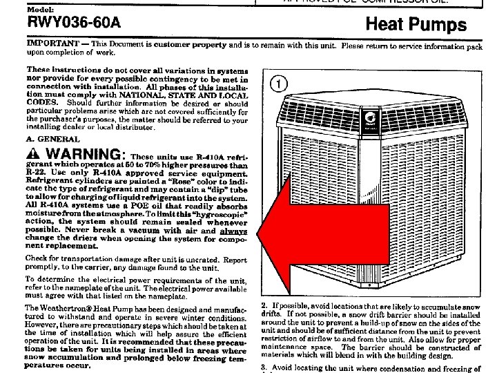
Page 2
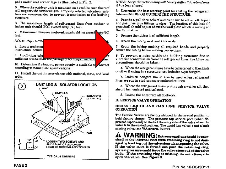
Page 3
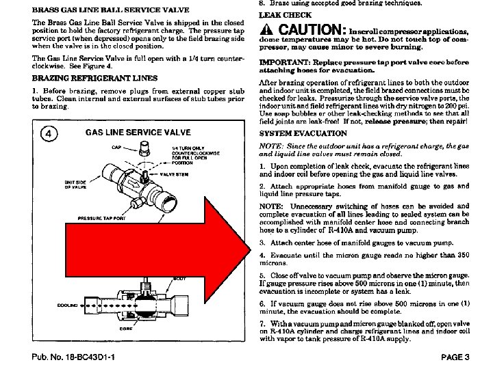
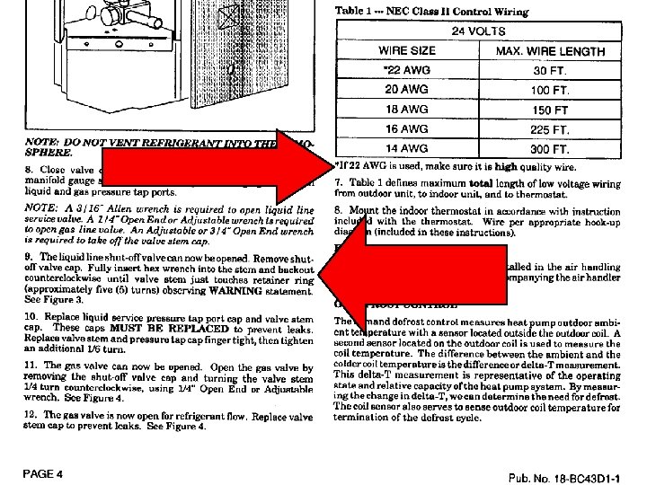
Page 4
• Sensing bulb location
• YES
SYSTEM CHARGING • Complete low side charging is not recommend in any system. It is time consuming, and if the servicer rushes the unit by adding liquid refrigerant, compressor damage could result. • Rapid low side charging of a scroll, with power off, could result in the scroll flanks sealing axially, preventing rotation. Once the system is equalized, the scroll will start.
SYSTEM CHARGING • The subcooling method is required when charging TXV systems. • Charging charts are included in the Service Facts document that come with the outdoor equipment. • Remember to allow sufficient time for the system to stabilize before adjusting the refrigerant charge.
Charging with R-410 A • In the vapor state a blended refrigerant may fractionate • Charge with liquid in the low side. – Put vapor into the low side. Use a metering device
SYSTEM CHARGING *When charging with liquid on the low side of a system, use a commercial type metering device in the manifold hose. i. e. Chargefaster (CH 200) made by Watsco, or equivalent.
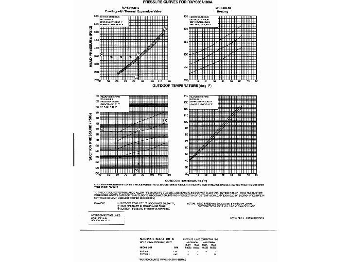
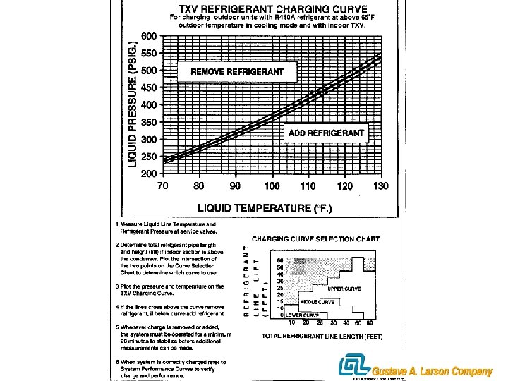
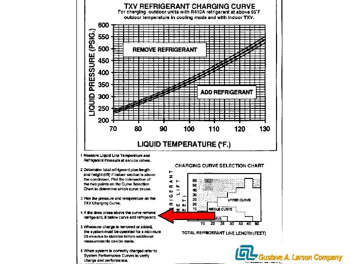
Charging by the Subcooling Method • All of our R-410 A systems are TXV metered at this time. • You must get an accurate temperature reading on the liquid line. – Use an electronic sensor and insulate it. • Use the charts shipped with the unit. • Allow a lot of time for charging, charge a little and wait.
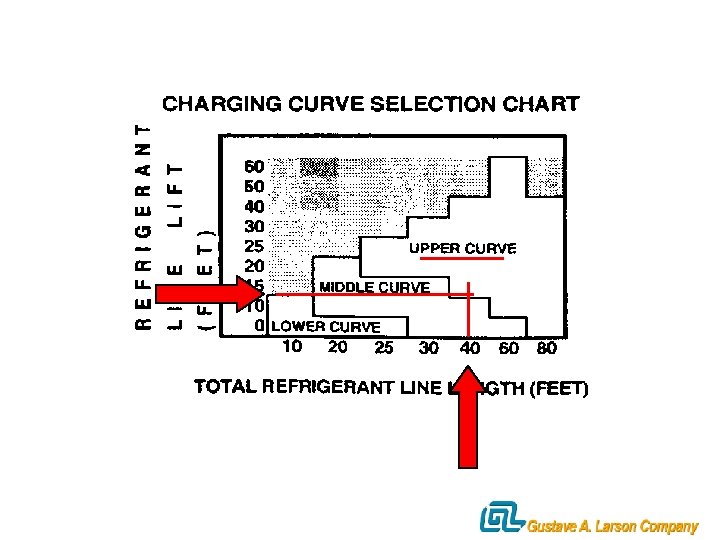
Using the Charging Chart • Measure temperature and pressure at liquid line. • Use line length & lift to choose which curve to use. • Plot the intersection of temp. & pressure. • If above the curve, remove refrigerant. • If below, add refrigerant • Wait 20 minutes to stabilize.
(390 PSIG & 115º F)
Sub-Cooling & Superheat Calculation Explained · Use the following chart to show to calculate Sub-Cooling and Superheat · First chart is a Properly Charged system · Sub-Cooling indicates amount of refrigerant STORED in the condensing unit
Sub-Cooling & Superheat Calculation Explained · Low Sub-Cooling indicates LOW-charge · High Sub-Cooling reading indicates OVERcharge (or possible Liquid Line restriction) · Rule of thumb = 10 - 15 degrees of sub-cooling Manufactures’ usually design to 10 degrees · Lower Heat Pump’s sub-cooling down to 10 - 13 degrees if high head problems occur
Sub-Cooling & Superheat Calculation Explained · Superheat indicates that complete vaporization of liquid refrigerant in the evaporator coil has taken place · Low Superheat means liquid refrigerant is present at or near the outlet of the evaporator · Compressor Damage is immanent · High Superheat means liquid is boiling off too soon and could mean evaporator is starved
SL Temperature minus - SL Pres. To Saturation equals = 55 45° 10° Sub-cooling & Superheat Calculation Explained Superheat 76 # 220 # Outdoor Coil Indoor Coil Sensible Latent Saturated Vapor Low Pres. Liquid High Pressure, Sub-cooled Liquid Latent Sensible Saturated Vapor High Pressure, High Temperature Vapor Sensible Superheated Vapor LL Pres. to Saturation minus - Basic Refrigeration Circuit Properly Charged Unit LL Temperature equals = 108° 98° 10° Sub-cooling
Over-Charged System · High Sub-Cooling reading indicates excessive amount of refrigerant in the condenser coil · Head pressure reading will be high · Saturation temperature will be high · Liquid line temperature at or near ambient · Unit will use excessive wattage to do the same amount of work · If TXV is working properly, work at indoor coil will be basically the same as properly charged system and Superheat will be normal
SL Temperature minus - SL Pres. To Saturation equals = 55 45° 10° Sub-cooling & Superheat Calculation Explained Superheat 76 # 316 # Outdoor Coil Indoor Coil Sensible Latent Saturated Vapor Low Pres. Liquid High Pressure, Sub-cooled Liquid Latent Sensible Saturated Vapor High Pressure, High Temperature Vapor Sensible Superheated Vapor LL Press. to Saturation minus - Basic Refrigeration Circuit Over Charged Unit LL Temperature equals = 135° 118° 17° Sub-cooling
Under-Charged System · Low Sub-Cooling reading indicates lack of refrigerant in the condenser coil. · Head pressure reading will be low · Saturation temperature will be low · Liquid line temperature will be high · Unit will use excessive wattage due to do extended run times to do the same work · TXV will not work properly, due to lack of “liquid seal” resulting in capacity loss · Superheat will be high - coil starved.
SL Temperature minus - SL Pres. To Saturation equals = 68 26° 42° Sub-cooling & Superheat Calculation Explained Superheat 50 # 182 # Outdoor Coil Indoor Coil Sensible Latent Saturated Vapor Low Pres. Liquid High Pressure, Sub-cooled Liquid Latent Sensible Saturated Vapor High Pressure, High Temperature Vapor Sensible Superheated Vapor LL Press. to Saturation minus - Basic Refrigeration Circuit Under Charged Unit LL Temperature equals = 95° 0° Sub-cooling
Real Life Charging Procedures. Expansion Valve Systems · First Things First! · Clean coils (indoor and outdoor) · Check air filters · Do Air Flow check. · Use Engineering Data for reference · Humid climates demand it · Full unit capacity depends on it
Real Life Charging Procedures · Indoor temp. needs to be between 70º - 80º · Run system for 10 minutes to stabilize · Check system Superheat · Measure suction line temperature at outdoor unit · Convert suction line pressure to saturation (read directly off of gauges or use pressure-temperature chart) · Suction line temperature minus saturation temperature = System Superheat · Nominal range = 15º - 25º, measured @ O. D. unit
Real Life Charging Procedures · You’re now only halfway finished! · Next, Check System Sub-cooling · measure the Liquid Line temperature · Convert Liquid Line pressure to saturation (read directly off of gauges or use pressure-temperature chart) · Saturation temperature minus Liquid Line temperature = Sub-cooling · Nominal range = 10º - 15º
What Does All That Mean? · Low Superheat readings indicate · Low Airflow · Dirty coils · Dirty air filter · Wrong blower speed · Faulty metering device, or improper size too large · Possible overcharge (suspect last)
What Does All That Mean? · High Superheat readings indicate · Too much airflow · Wrong blower speed · Faulty metering device, or improper size too small, improperly adjusted · Power element w/ low or no charge · Valves fail shut with no charge in power element · Possible undercharge (suspect last)
What Does All That Mean? · High Sub-cooling readings indicate · Restriction at the. . . · Liquid Line filter · Metering device in the evaporator · Possible overcharge (only if superheat is normal as indicated by above) · Low Sub-cooling readings indicate · Undercharge (proven by high superheat readings) · Sub-cooling below 10º indicates low charge · Sub-cooling above 15º indicates over-charge
Diagnostics • Outdoor circuit diagnostics • Indoor circuit diagnostics • Circuit accessories – – Receivers Accumulators Filter driers Sight glasses
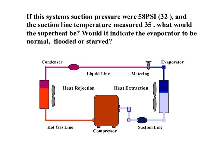
If this system’s discharge pressure was 200 PSI (102 ), and the liquid line temperature leaving the condenser coil was 82. What would the subcool be? Would it indicate your condenser is normal, flooded or starved? Condenser Drier Liquid Line Heat Rejection Hot Gas Line Compressor Metering Heat Extraction Suction
There are three times to troubleshoot a system! • On a service call – Most expensive – Reputation on the line – Repairs the most time consuming to make.
• On start up – Time consuming checking temperatures and pressures – Must figure this time into job. – Repairs made now can save money in the long run
• During bidding process – Customer pays bill – Customer is made aware of possible expenses up front – You come off as one who knows more than the competition
Internal Parts Process Tube Bulb Leak Power Head Diaphragm Product Overheating Equalizing Line
Other Monitored TXV Failures • Dead Element • Super Heat Setting • Field Disassembled • Field Damage • Internal Diaphragm • Foreign Matter
Overheating Fatigued Tubing Sensing Bulb Cut Overheating
Material Defect 1 Unit Incorrect Assembly 1% Leak-Element Cap Tube 1% Dead Element 1% Misc. Field Damage 1% Disassembled in Field 2% Leak-Char Lea k-B Fo ulb ging Tip 9 % re ign Ma t 11% Overheated Broken Ca p Tub 19% te r No Failure 36% etting ct S Incorre 10%
Stuck contacts 13. 0% Coil open 4. 5% Noisy 6. 5% Stuck plunger 4. 5% Misc. 11. 5% 40% Relay Issues No Fault 60%
Low Voltage Relay • Uses sealed circuit board relays • Uses same terminals as previous electromechanical relay A B • Has a surge protector to prevent electrical transient damage (Voltage Spikes) 6 T 4 • Replaces old relay in the field Fan Relay Terminals
Trane/Am. Std Training CD-Program Publication #34 -3416 -01 Mechanical Refrigeration Troubleshooting R-22/R-410 A
#1 Reason To Buy A Warranty