Chapter 6 Multiplexing Why Multiplexing Observations Most individual

Chapter 6 Multiplexing

Why Multiplexing? Observations • Most individual data communicating devices typically require modest data rate. • Communication media usually have much higher bandwidth. • Two communicating stations do not utilize the full capacity of a data link. • The higher the data rate the most cost effective is the transmission facility

Multiplexing • It allows several transmission sources to share a larger transmission capacity (single data link) • Multiplexer (MUX): which combines them into a single stream • Demultiplexer (DEMUX) : which separates the stream back into its component transmission (one to

Categories of multiplexing 4

Frequency Division Multiplexing • FDM is an analog multiplexing technique that combines analog signals • A number of signals can be carried simultaneously • Signals generated by each sending device modulate different carrier frequency • Signals are then combined into a single composite signal • Carrier frequencies are separated by sufficient bandwidth and do not overlap —e. g. broadcast radio • Channel allocated even if no data 5

FDM Diagram 6

How FDM is Implemented • Divide the available bandwidth of a single physical medium into a number of smaller , independent frequency channels. • Using modulation, independent message signals are translated into different frequency bands. • All the modulated signals are combined in a linear summing circuit to form a composite signal for transmission. • The carriers that are used to modulate individual massage signals are called sub-carriers.
")
FDM process • Modulate different carrier frequencies (f 1, f 2, and f 3) • The resulting modulated signals are then combined into a single composite signal 8

FDM demultiplexing example • the individual signals are then passed to a demodulator that separates them from their carriers and passes them to the output lines 9

Applications of FDM §Transmission of AM/ FM radio broadcasting §TV broadcasting §Cable television §https: //www. ques 10. com/p/37223/explain-fdm-with-a-neat-blockdiagram-give-its-app/

Time Division Multiplexing 11

Time Division Multiplexing • It is a digital process that allows several connections to share the high BW of the link • Instead of sharing BW as in FDM, time is shared • Each connection occupies a portion of time in the link • Portions of signals occupy the link sequentially (1, 2, 3, 4) • Data in a message from source 1 always go to specific destination like 1, 2, 3, 4 • Digital data from different sources are combined into one timeshared link • It does not mean that the sources cannot produce analog data, analog data can be sampled and changed to digital data

Note: TDM is a digital multiplexing technique for combining several low rate channels into high rate one We can divide TDM into two different schemes: Synchronous and statistical 13

Time slots & frames • The data flow of each input connection is divided into units, where each input occupies one input time slot • A unit can be 1 bit, 1 character or 1 block of data • If an input time slot is T s, each output slot is T/n s, where n is the number of connections • A round of data units from each input connection is collected into frame 14

15

Note: In a Synchronous TDM, the data rate of the link is n times faster, and the unit duration is n times shorter. 16

Figure 6. 21 Multiplexing and inverse multiplexing 46

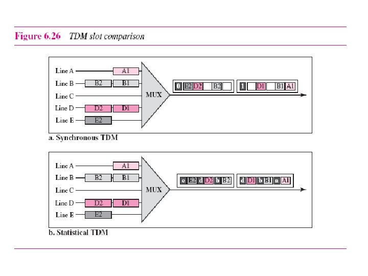
Statistical TDM üIn synchronous TDM, each input has a reserved slot in the output frame. üThis can be inefficient if some input lines have no data to send. üIn Statistical TDM, slots are dynamically allocated to improve bandwidth efficiency. üIn statistical multiplexing, the number of slots in each frame is less than the number of input lines. üThe multiplexer checks each input line in round robin fashion, it allocates a slot for an input line if the line has data to send; otherwise, it skips the line and checks the next line. 47
- Slides: 19