Multiplexing Multiplexing Definition Multiplexing is the set of


 2. wavelength-division")
")


")


 is designed to use the high-data-rate capability of fiber-optic")


 is a digital process that allows several connections to share")


 Output bit duration = Input bit duration for each connection /")


- Slides: 40
Multiplexing
Multiplexing �Definition: Multiplexing is the set of techniques that allows the simultaneous transmission of multiple signals across a single data link.
Why Multiplexing? �Whenever the transmission capacity of a medium linking two devices is greater than the transmission needs of the devices, the link can be shared in order to maximize the utilization of the link. �such as one cable can carry a hundred channels of TV.
Type of multiplexing
Type of multiplexing �There are three basic techniques: 1. Frequency-Division Multiplexing (FDM) 2. wavelength-division multiplexing 3. Time-Division Multiplexing (TDM)
Frequency-Division Multiplexing �An analog technique. �Applied when the bandwidth of a link (in hertz) is greater than the combined bandwidths of the signals to be transmitted. �In FDM, signals generated by each sending device modulate different carrier frequencies. �These modulated signals are then combined into a single composite signal that can be transported by the link.
Frequency-Division Multiplexing �Carrier frequencies are separated by sufficient bandwidth to accommodate the modulated signal. �These bandwidth ranges are the channels through which the various signals travel. �Channels can be separated by strips of unused bandwidth-guard bands-to prevent signals from overlapping.
Frequency-Division Multiplexing
Frequency-Division Multiplexing �FDM is an analog multiplexing technique that combines analog signals.
Multiplexing process(FDM Process)
Demultiplexing Process
The analog carrier system �To maximize the efficiency of their infrastructure, telephone companies have traditionally multiplexed signals from lower-bandwidth lines onto higherbandwidth lines. In this way, many switched or leased lines can be combined into fewer but bigger channels.
The analog carrier system �For analog lines, FDM is used. �One of these hierarchical systems used by AT&T is made up of groups, supergroups, master groups, and jumbo groups.
Analog hierarchy
Analog hierarchy � 12 voice channels are multiplexed onto a higherbandwidth line to create a group. �A group has 48 k. Hz of bandwidth and supports 12 voice channels. �At the next level, up to five groups can be multiplexed to create a composite signal called a supergroup. � A supergroup has a bandwidth of 240 k. Hz and supports up to 60 voice channels.
Analog hierarchy �Supergroups can be made up of either five groups or 60 independent voice channels. �At the next level, 10 supergroups are multiplexed to create a master group. � A master group must have 2. 40 MHz of bandwidth, but the need for guard bands between the supergroups increases the necessary bandwidth to 2. 52 MHz. � Master groups support up to 600 voice channels.
Analog hierarchy �Finally, six master groups can be combined into a jumbo group. A jumbo group must have 15. 12 MHz (6 x 2. 52 MHz) but is augmented to 16. 984 MHz to allow for guard bands between the master groups.
Wavelength-Division Multiplexing �Wavelength-division multiplexing (WDM) is designed to use the high-data-rate capability of fiber-optic cable. �The optical fiber data rate is higher than the data rate of metallic transmission cable. �Using a fiber-optic cable for one single line wastes the available bandwidth.
Wavelength-Division Multiplexing �Multiplexing allows us to combine several lines into one. �WDM is conceptually the same as FDM, except that the multiplexing and Demultiplexing involve optical signals transmitted through fiber-optic channels.
Wavelength-Division Multiplexing �The idea is the same: �We are combining different signals of different frequencies. The difference is that the frequencies are very high.
TDM �Time-division multiplexing (TDM) is a digital process that allows several connections to share the high bandwidth of a link. �Each connection occupies a portion of time in the link. �TDM is, in principle, a digital multiplexing technique. �Digital data from different sources are combined into one timeshared link. �However, this does not mean that the sources cannot produce analog data; analog data can be sampled, changed to digital data, and then multiplexed by using TDM
TDM
TDM
TDM �We can divide TDM into two different schemes: �Synchronous �Statistical
Synchronous TDM �In synchronous TDM, the data flow of each input connection is divided into units, where each input occupies one input time slot. �A unit can be 1 bit, one character, or one block of data. �Each input unit becomes one output unit and occupies one output time slot. �However, the duration of an output time slot is n times shorter than the duration of an input time slot. �If an input time slot is T s, the output time slot is Tin s, where n is the number of connections. �In other words, a unit in the output connection has a shorter duration; it travels faster.
Synchronous TDM �A round of data units from each input connection is collected into a frame. �If we have n connections, a frame is divided into n time slots and one slot is allocated for each unit, one for each input line. �If the duration of the input unit is T, the duration of each slot is Tin and the duration of each frame is T. �The data rate of the output link must be n times the data rate of a connection to guarantee the flow of data.
TDM Example Lets suppose there are 3 input connections having data rate of 1 kbps from each connection. If we have to multiplex 1 bit from each connection then what is the time duration for (a) each input slot (b) each output slot (c) each frame Solution: (a) The bit duration for each connection (Tb) = 1 / Data Rate = 1 / 1000 b/s = 0. 001 sec = 1 msec. Since the we have to multiplex 1 bit at a time from each connection, the duration for each input slot = 1 ms
Synchronous TDM (b) Output bit duration = Input bit duration for each connection / number of connections = 1 / 3 ms (c) The frame rate is always same as the input bit rate. Hence Frame rate = 1 ms (d) Output bit rate = 1 / Output bit duration = 1 / (1/3 ms) = 3 kbps OR Output bit rate = Input bit rate x no. of connections = 1 kbps x 3 = 3 kbps
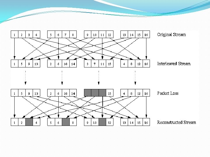
Interleaving �Interleaving is the process of distributing consecutive bits of a block into different sub blocks. �If a sequence in one sub block is corrupted then these bits will not be consecutive in the original block.
Data Rate Management �One problem with TDM is how to handle a disparity in the input data rates. �In all our discussion so far, we assumed that the data rates of all input lines were the same. �However, if data rates are not the same, three strategies, or a combination of them, can be used. �We call these three strategies �multilevel multiplexing, �multiple-slot allocation, and �pulse stuffing.
Multilevel Multiplexing �Multilevel multiplexing is a technique used when the data rate of an input line is a multiple of others. �For example we have two inputs of 20 kbps and three inputs of 40 kbps. �The first two input lines can be multiplexed together to provide a data rate equal to the last three. �A second level of multiplexing can create an output of 160 kbps.
Multiple Slot Allocation �Sometimes it is more efficient to allot more than one slot in a frame to a single input line. �For example, we might have an input line that has a data rate that is a multiple of another input. �In Figure 6. 20, the input line with a 50 -kbps data rate can be given two slots in the output. �Insert a serial-to-parallel converter in the line to make two inputs out of one.
Pulse Stuffing Serial-to. Parallel Converter
Pulse Stuffing �Sometimes the bit rates of sources are not multiple integers of each other. �Therefore, neither of the above two techniques can be applied. �One solution is to make the highest input data rate the dominant data rate and then add dummy bits to the input lines with lower rates. �This will increase their rates. �This technique is called pulse stuffing, bit padding, or bit stuffing. �The input with a data rate of 46 is pulse-stuffed to increase the rate to 50 kbps.
Pulse Stuffing
Frame Synchronization �The implementation of TDM is not as simple as that of FDM. �Synchronization between the multiplexer and de-multiplexer is a major issue. �If the multiplexer and the de-multiplexer are not synchronized, a bit belonging to one channel may be received by the wrong channel. �For this reason, one or more synchronization bits are usually added to the beginning of each frame. �These bits, called framing bits. �Framing bits allows the de-multiplexer to synchronize with the incoming stream so that it can separate the time slots accurately. �Frame bit consists of 1 bit per frame, alternating between 0 and 1.
Statistical Time-Division Multiplexing �In statistical time-division multiplexing, slots are dynamically allocated to improve bandwidth efficiency. �Only when an input line has a slot's worth of data to send is it given a slot in the output frame. �In statistical multiplexing, the number of slots in each frame is less than the number of input lines. �The multiplexer checks each input line in round robin fashion; it allocates a slot for an input line if the line has data to send; �otherwise, it skips the line and checks the next line.
�Since a slot carries both data and an address in statistical TDM, the ratio of the data size to address size must be reasonable to make transmission efficient. �There is another difference between synchronous and statistical TDM, but this time it is at the frame level. �The frames in statistical TDM need not be synchronized, so we do not need synchronization bits. �In statistical TDM, the capacity of the link is normally less than the sum of the capacities of each channel. �The designers of statistical TDM define the capacity of the link based on the statistics of the load for each channel.
Thank you