Multiplexing Chapter3 Multiplexing Multiplexing is a technique used


 available at")


 each of the three voice channels to a different")


 TDM ii) FDM")


- Slides: 41
Multiplexing Chapter-3
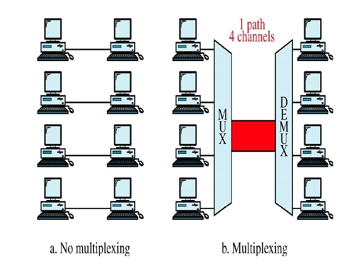
Multiplexing • Multiplexing is a technique used to combine and send the multiple data streams over a single medium. • The process of combining the data streams is known as multiplexing and hardware used for multiplexing is known as a multiplexer. • Multiplexing is achieved by using a device called Multiplexer (MUX) that combines n input lines to generate a single output line. • Multiplexing follows many-to-one, i. e. , n input lines and one output line.
Demultiplexing • Demultiplexing is achieved by using a device called Demultiplexer (DEMUX) available at the receiving end. • DEMUX separates a signal into its component signals (one input and n outputs). Therefore, we can say that demultiplexing follows the one-to-many approach.
Why Multiplexing? • If there are multiple signals to share one medium, then the medium must be divided in such a way that each signal is given some portion of the available bandwidth. • For example: If there are 10 signals and bandwidth of medium is 100 units, then the 10 unit is shared by each signal. • When multiple signals share the common medium, there is a possibility of collision. Multiplexing concept is used to avoid such collision.
Advantages of Multiplexing: • More than one signal can be sent over a single medium. • The bandwidth of a medium can be utilized effectively.
Types of Multiplexing
Define multiplexing. List its type. • Multiplexing is the process in which multiple data streams, coming from different sources, are combined and transmitted over a single data channel or data stream. • The following three major multiplexing techniques: • Frequency division multiplexing • Wavelength division multiplexing • Time division multiplexing
State advantages of multiplexing. • Advantages of multiplexing: 1. Simple and easy 2. Large capacities and scalable. 3. Signals from different sources can be sent together through a single common channel. 4. Signals may have varying speed.
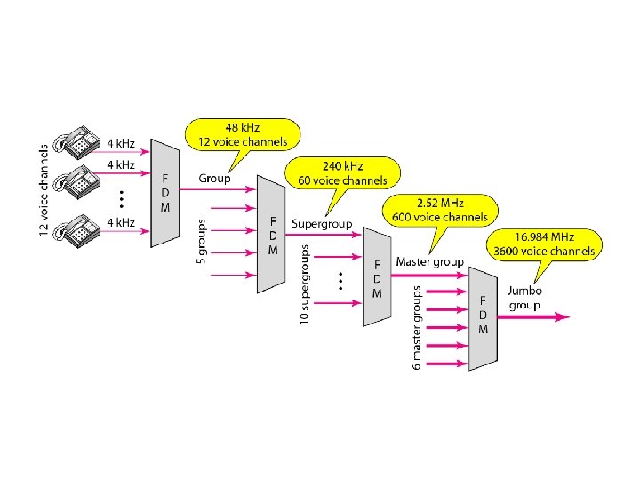
Frequency Division Multiplexing • It is an analog technique. • Signals of different frequencies are combined into a composite signal and is transmitted on the single link. • Bandwidth of a link should be greater than the combined bandwidths of the various channels. • Each signal is having different frequency. • Channels are separated by the strips of unused bandwidth called Guard Bands (to prevent overlapping).
Frequency Division Multiplexing
FDM Process • Each source generates a signal of a similar frequency range. • Inside the multiplexer, these similar signals modulate different carrier frequencies ( f 1, f 2, and f 3). • The resulting modulated signals are then combined into a single composite signal that is sent out over a media link that has enough bandwidth to accommodate it.
Demultiplexing Process • The demultiplexer uses a series of filters to decompose the multiplexed signal into its constituent component signals. • The individual signals are then passed to a demodulator that separates them from their carriers and passes them to the output lines.
Question • Assume that a voice channel occupies a bandwidth of 4 k. Hz. We need to combine three voice channels into a link with a bandwidth of 12 k. Hz, from 20 to 32 k. Hz. Show the configuration, using the frequency domain. Assume there are no guard bands.
• We shift (modulate) each of the three voice channels to a different bandwidth, as shown in Figure. • We use the 20 - to 24 -k. Hz bandwidth for the first channel, the 24 - to 28 -k. Hz bandwidth for the second channel, and the 28 - to 32 -k. Hz bandwidth for the third one. Then we combine them.
Question • Five channels, each with a 100 -k. Hz bandwidth, are to be multiplexed together. What is the minimum bandwidth of the link if there is a need for a guard band of 10 k. Hz between the channels to prevent interference?
Solution • For five channels, we need at least four guard bands. This means that the required bandwidth is at least • 5 × 100 + 4 × 10 = 540 k. Hz
Five channels each with 200 k. Hz bandwidth are multiplexed using FDM. Find minimum bandwidth of the link if guard band of 10 k. Hz is used. • Five channels each with 200 k. Hz bandwidth are multiplexed using FDM. • For five channels, we need at least four guard bands. • Guard Bands of 10 KHz is used. • This means that the required bandwidth is atleast : • 5*200+4*10=1040 KHz.
Applications of FDM • FDM is used for FM & AM radio broadcasting. • FDM is used in television broadcasting. • First generation cellular telephone also uses FDM.
Wavelength-Division Multiplexing • WDM is an analog multiplexing technique. • Working is same as FDM. • In WDM different signals are optical or light signals that are transmitted through optical fiber. • Various light waves from different sources are combined to form a composite light signal that is transmitted across the channel to the receiver. • At the receiver side, this composite light signal is broken into different light waves by Demultiplexer.
• The Combining and the Splitting of light waves is done by using a PRISM. Prism bends beam of light based on the angle of incidence and the frequency of light wave. One application of WDM is the SONET network, in which multiple optical fiber lines are multiplexed and demultiplexed.
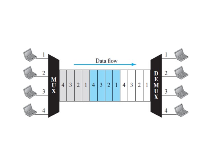
Time-Division Multiplexing • It is the digital multiplexing technique. • Channel/Link is not divided on the basis of frequency but on the basis of time. • Total time available in the channel is divided between several users. • Each user is allotted a particular time interval called time slot or slice. • In TDM the data rate capacity of the transmission medium should be greater than the data rate required by sending or receiving devices.
• We can divide TDM into two different schemes: 1. Synchronous and 2. Statistical (Asynchronous)
• Explain process of synchronous time division multiplexing with its advantages.
Synchronous TDM or TDM • In the technique, the time slice is allocated to a source node regardless of whether it wants to send some data or not. • This is a fairly simple mechanism to identify, at a destination node, which data originated from which source node, since every source node has a fixed time slot. • Therefore, the position of the data within the data frame specifies its origin. • However, it can be a very wasteful scheme, because the time slot is allotted to a source node even if it has nothing to send.
• A small buffer memory is associated with every source node. • At any time, not all nodes may want to send some data. • Regardless of this, the timing device in the multiplexer allocates some time for each node to transmit the data from its buffer, and then repeats this cycle.
• E. g. If there is no data to be transmitted, the buffer will be empty but still the turn of the node will come. • Advantages: • An order is maintained • No addressing information is required, channel capacity should be large.
• Explain the process of asynchronous TDM with example.
Asynchronous TDM: 1. It is also known as statistical time division multiplexing. 2. Asynchronous TDM is called so because is this type of multiplexing, time slots are not fixed i. e. the slots are flexible. 3. Here, the total speed of input lines can be greater than the capacity of the path. 4. In synchronous TDM, if we have n input lines then there are n slots in one frame. But in asynchronous it is not so. 5. In asynchronous TDM, if we have n input lines then the frame contains not more than m slots, with m less than n (m < n). 6. In asynchronous TDM, the number of time slots in a frame is based on a statistical analysis of number of input lines.
7. In this system slots are not predefined, the slots are allocated to any of the device that has data to send. 8. The multiplexer scans the various input lines, accepts the data from the lines that have data to send, fills the frame and then sends the frame across the link. 9. If there are not enough data to fill all the slots in a frame, then the frames are transmitted partially filled.
• In statistical multiplexing, there is no fixed relationship between the inputs and outputs because there are no pre-assigned or reserved slots. • We need to include the address of the receiver inside each slot to show where it is to be delivered. • The addressing in its simplest form can be n bits to define N different output lines. • For example, for eight different output lines, we need a 3 -bit address.
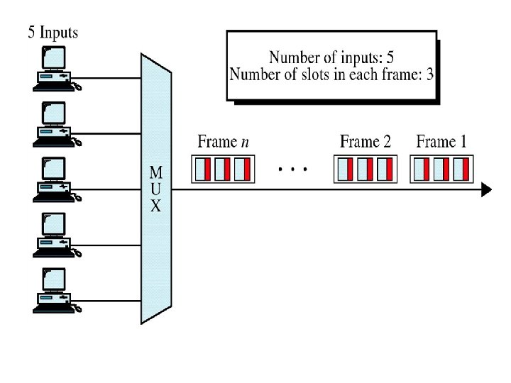
• Example: • Asynchronous Time Division Multiplexing is depicted in fig. • Here we have five input lines and three slots per frame. 1. Case 1, only three out of five input lines place data onto the link i. e. number of input lines and number of slots per frame are same.
2. In Case 2, four out of five input lines are active. Here number of input line is one more than the number of slots per frame.
3. In Case 3, all five input lines are active. • In all these cases, multiplexer scans the various lines in order and fills the frames and transmits them across the channel. • The distribution of various slots in the frames is not symmetrical. In case 2, device 1 occupies first slot in first frame, second slot in second frame and third slot in third frame.
Explain the following multiplexing techniques with block diagram: i) TDM ii) FDM
• Give the difference between TDM & FDM. Or • Compare TDM & FDM
PARAMETER TDM FDM Definition TDM is the transmission technique FDM is the transmission technique in which different signal are transmitted over a common channel and each signal occupies different entire range of bandwidth in the slot within that bandwidth of the time domain. frequency domain. Stands For Time-Division Multiplexing Useful for TDM can be used for both Analog FDM can be used for Analog and Digital signals only. Frequency-Division Multiplexing Synchronization TDM requires Synchronization. not required Synchronization. Circuit circuitry is very simple to built. FDM circuitry is very complex. Cross Talk TDM is not sensitive for Cross Talk (Noise Immunity) FDM suffers from the cross talk immunity due to Bandpass Filter. Requirement TDM requires sync pulse for its operation. FDM requires Guard bands for its operation. Effiecient TDM is more efficient and is widely used technique in multiplexing. FDM is less efficient compared to TDM. Applications TDM is used in Pulse code modulation. FDM is used in TV and RADIO broadcasting.