Challenges of cost effective screening of current and




- Slides: 42
Challenges of cost effective screening of current and future TMR/PMR design heads Henry Patland President & CEO hpatland@us-isi. com www. us-isi. com
Abstract As the industry makes the transition to PMR technology, with expected 100% transition by 2010, there are many challenges that head designers need to overcome to make this transition successful. In addition to dealing with completely new head, media and channel designs, head manufacturers have to quickly anticipate the type of failures they will see from new head designs in volume production environments and be ready to cost effectively screen out those failures. This presentation will concentrate on the challenges of testing these new head technologies, the type of solutions that are currently available and future requirements. Also a cost effective test strategy will be presented for discussion.
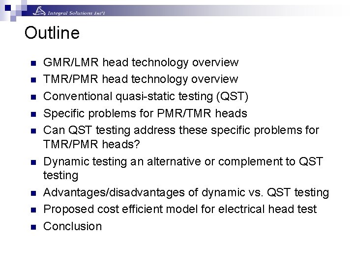
Outline n n n n n GMR/LMR head technology overview TMR/PMR head technology overview Conventional quasi-static testing (QST) Specific problems for PMR/TMR heads Can QST testing address these specific problems for TMR/PMR heads? Dynamic testing an alternative or complement to QST testing Advantages/disadvantages of dynamic vs. QST testing Proposed cost efficient model for electrical head test Conclusion
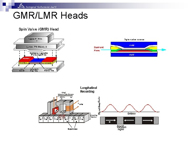
GMR/LMR Heads
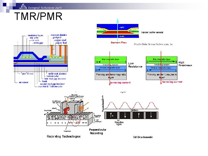
TMR/PMR
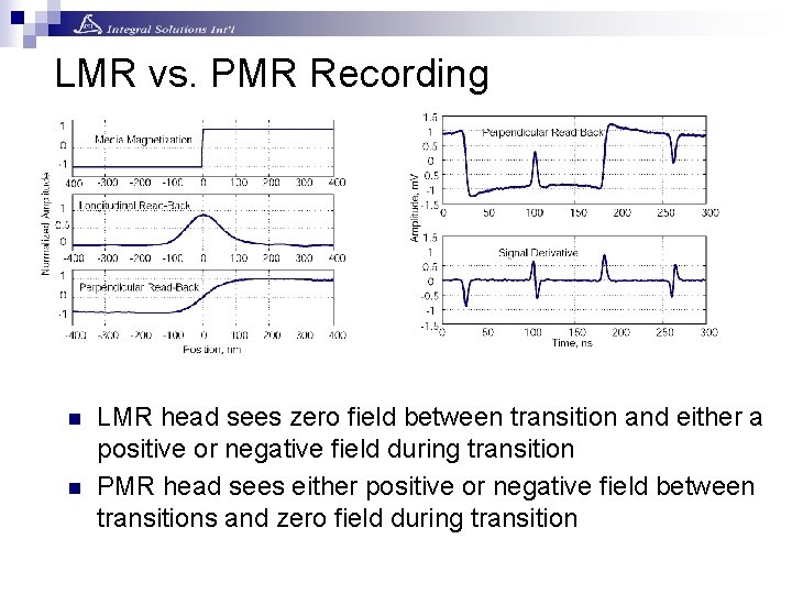
LMR vs. PMR Recording n n LMR head sees zero field between transition and either a positive or negative field during transition PMR head sees either positive or negative field between transitions and zero field during transition
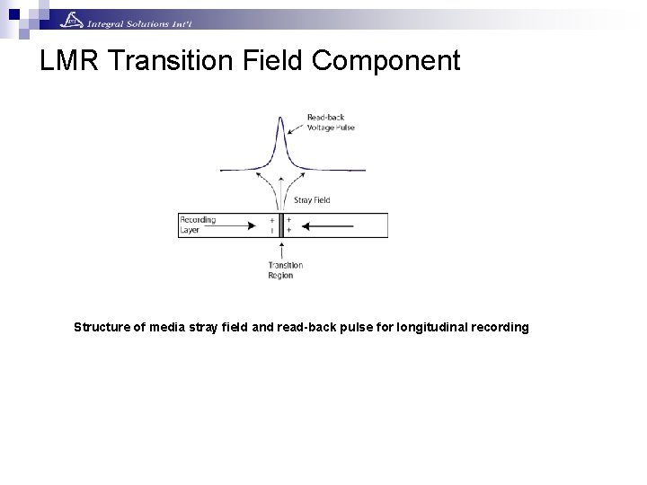
LMR Transition Field Component Structure of media stray field and read-back pulse for longitudinal recording
PMR Transition Field Component Media stray fields for perpendicular media with soft under-layer U-Shape bending caused by Perpendicular Stray Field
Low Frequency Cut-off in PMR Read-back of low density perpendicular square wave pattern with different LF cut-off frequency: Signal shape distortions
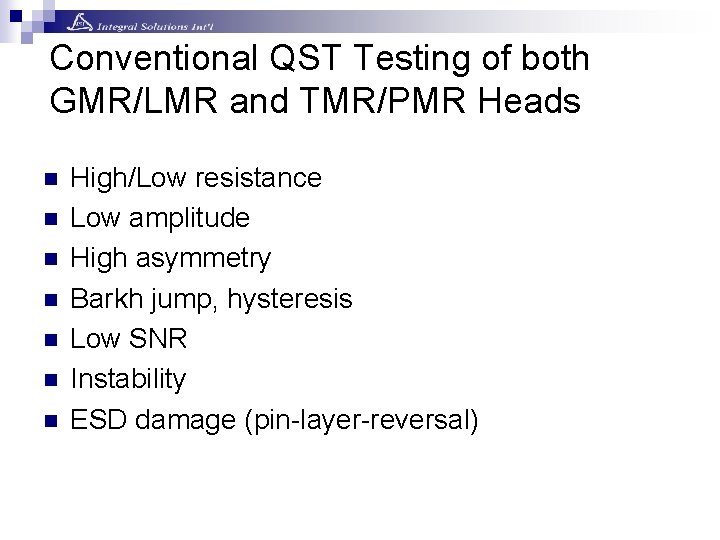
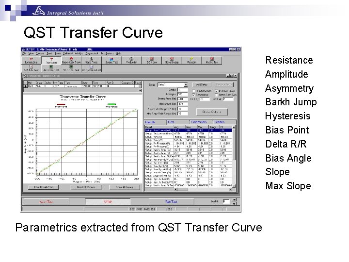
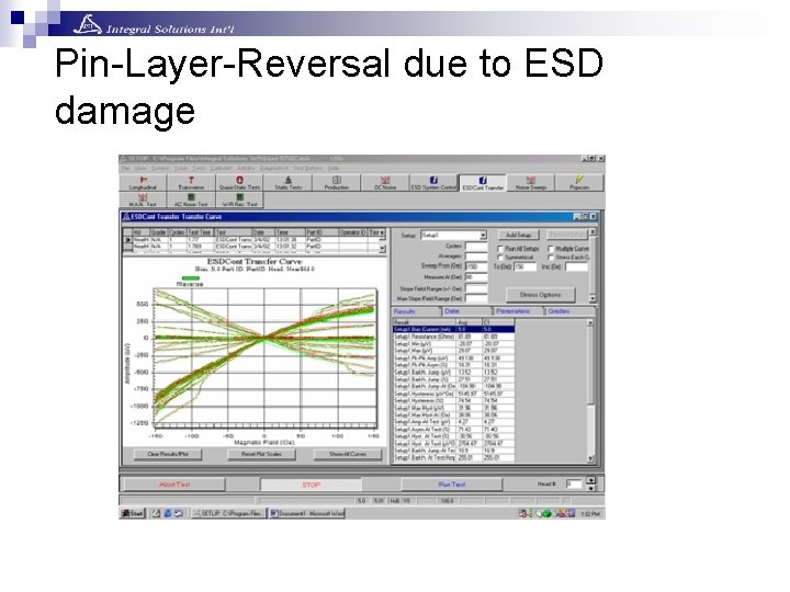
Conventional QST Testing of both GMR/LMR and TMR/PMR Heads n n n n High/Low resistance Low amplitude High asymmetry Barkh jump, hysteresis Low SNR Instability ESD damage (pin-layer-reversal)
QST Transfer Curve Resistance Amplitude Asymmetry Barkh Jump Hysteresis Bias Point Delta R/R Bias Angle Slope Max Slope Parametrics extracted from QST Transfer Curve
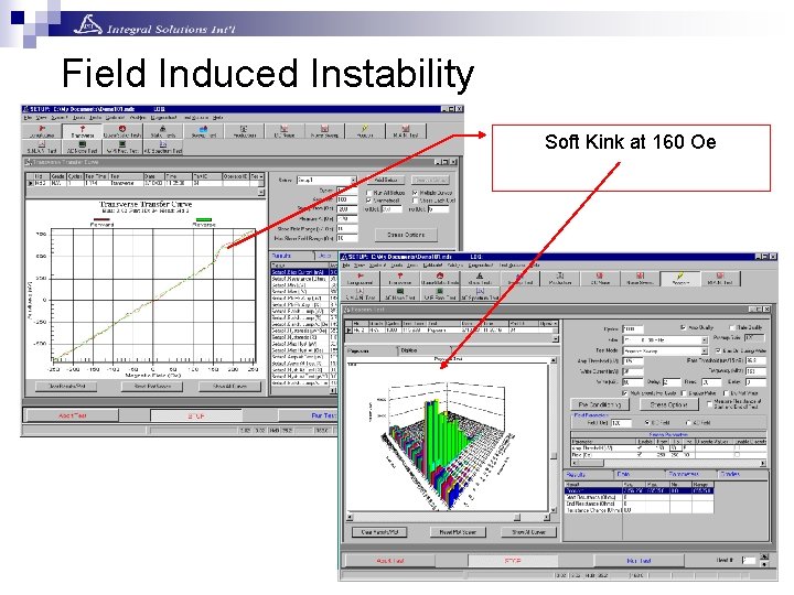
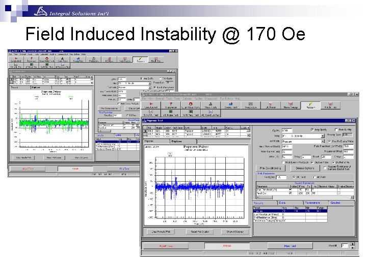
Field Induced Instability Soft Kink at 160 Oe
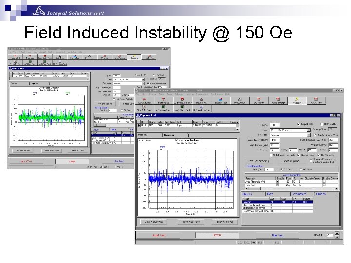
Field Induced Instability @ 150 Oe
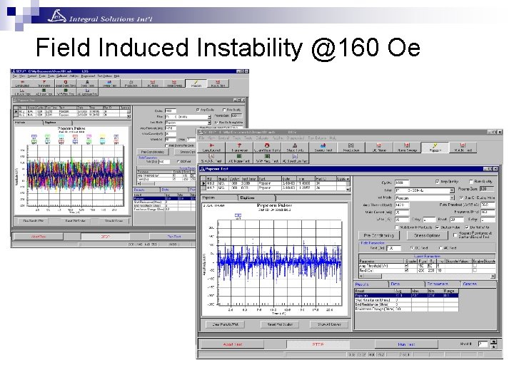
Field Induced Instability @160 Oe
Field Induced Instability @ 170 Oe
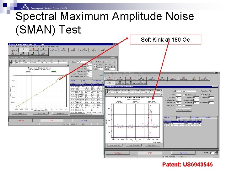
Spectral Maximum Amplitude Noise (SMAN) Test Soft Kink at 160 Oe Patent: US 6943545
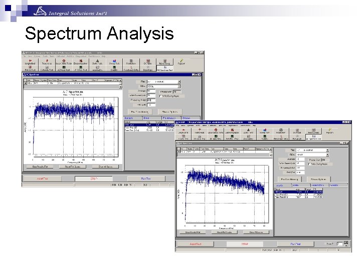
Spectrum Analysis
Pin-Layer-Reversal due to ESD damage
QST has good track record at conventional testing. Can QST testing address TMR/PMR Specific Problems?
PMR/TMR Specific Problems and Using QST Test Strategy n n n Pin-holes and µSmearing on insulating spacer Instability with lower cut off frequency Weak pin-layer Stray side field sensitivity and larger shield geometries Writer pole problems
Problem: Pin-Hole & µSmearing Issues n Both Pin-Holes and µSmearing occur during manufacturing of TMR stacks with extremely thin insulation layer n Both Pin-Holes and µSmearing disrupt the tunneling mechanism and essentially create a short across the insulation layer n When Pin-Holes are present, some of the Bias current flows through the created shorts, and SNR is deteriorated n Additionally these shorts cause higher operating temperature of the TMR sensor which in turn causes reliability issues Pin-Holes or µSmearing
QST Solution: Pin-Hole & µSmearing Issues n By raising the TMR sensor temperature either through Bias Source or external means, and measuring the Resistance change, both Pin-Hole & µSmearing can be detected n Delta. R/R, Transfer Curve, Hysteresis, and Slope of Transfer Curve are also good indicators of Pin -Hole or µSmearing presence
Problem: Lower Frequency Instability n Since PMR heads see more low frequency component and are exposed to multiple state magnetic fields between transitions, the probability of magnetic field induced instability is increased n This type of instability can cause high BER or losing servo in the drive
QST Solution: Lower Frequency instability n By lowering the cut-off freq to 100 Khz from typical 3 -5 Mhz and using industry standard Spectral Maximum Amplitude Noise (SMAN) tests these unstable heads can be effectively screened out
Problem: Weakly Pinned Heads n If pinned layer is weak, the magnetization angle between pinned layer and free layer is compromised causing degraded Delta. R/R, SNR degradation and sensor instability
QST Solution: Weakly Pinned Heads n By testing heads at high magnetic fields and various angles, weakly pinned head can be screened out by QST n Weakly pinned heads might require additional reinitialization before final QST test
Problem: Stray Side Field sensitivity and New Larger Shield Geometries n Stray side field sensitivity can cause sensor saturation and transition shifts as caused by adjacent tracks n Larger shields absorb much of external magnetic field to shield the sensor and can also become magnetized causing sensor instability
QST Solution: Stray Side Field sensitivity and New Larger Shield Geometries n By testing QST with different magnetic field orientation, stray side field sensitivity can be simulated and sensitive heads can be screened out n By applying larger magnetic fields (typ: TMR/PMR – 500 to 600 Oe) the larger shields can be saturated to conventionally exercise the sensor
Problem: Writer Pole Design n Vertical Pole heads have poor write gradient n Write distortions when head is skewed with respect to track direction n Thin pole heads exhibit pole remnance problems due to magnetic domains in the pole tips (sometimes overwriting servo patterns)
QST Solutions: Writer Pole Design n With current technology QST is not capable of detecting this failure n Currently through improved writer pole material and geometry design, this issue is getting resolved
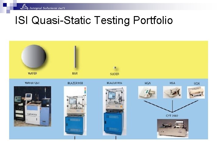
ISI Quasi-Static Testing Portfolio
Available Electrical Test Technologies n n Dynamic Testing Quasi-Static Testing
Dynamic Head Test Advantages n n n Tests both writer and reader Resembles closely final head/media arrangement Extensive tests such as MRR, Amp, Asym, NLTS, SNR, OW, PW 50, MRW, MWW, ATE, BER
Dynamic Head Test Disadvantages n n n n n High capital cost ($$$) Low UPH (typical 30 -40) Media quality/flying height variation Difficult to separate writer vs. reader failures Can only be done at HGA level, high scrap cost High operating cost Larger and higher class cleanroom required Higher ESD danger due to more handling Poor correlation to final HDD yield
QST Head Test Advantages n n n n Low capital cost ($) High UPH (typical 1000) Can be done at row level (early test equals lower scrap cost) Very detailed and effective reader testing with and without various stresses Good correlation to final reader related HDD Yield Low ESD risk due to automation Low operating cost Less clean room space and lower class cleanroom required
QST Head Test Disadvantages n n n Cannot characterize writer Cannot predict head/media interface problems since there is no flying No off-track analysis
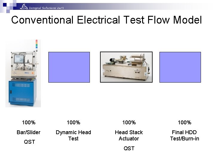
Conventional Electrical Test Flow Model 100% Bar/Slider Dynamic Head Test Head Stack Actuator Final HDD Test/Burn-in QST
Conventional Electrical Test Cost Model
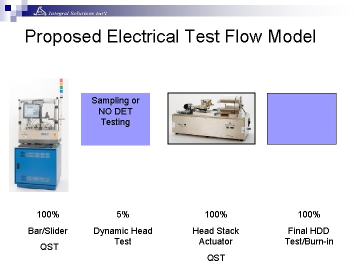
Proposed Electrical Test Flow Model Sampling or NO DET Testing 100% 5% 100% Bar/Slider Dynamic Head Test Head Stack Actuator Final HDD Test/Burn-in QST
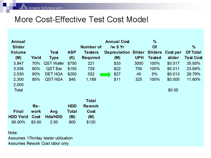
More Cost-Effective Test Cost Model
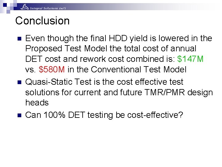
Conclusion n Even though the final HDD yield is lowered in the Proposed Test Model the total cost of annual DET cost and rework cost combined is: $147 M vs. $580 M in the Conventional Test Model Quasi-Static Test is the cost effective test solutions for current and future TMR/PMR design heads Can 100% DET testing be cost-effective?
References n n n Alexander Taratorin, “Magnetic Recording Systems and Measurements”, San Jose Research Center, HGST Bryan Oliver, Qing He, Xuefei Tang, and J. Nowaka), “Dielectric breakdown in magnetic tunnel junctions having an ultrathin barrier”, JOURNAL OF APPLIED PHYSICS VOLUME 91, NUMBER 7 Sangmun Oh 1, K. Nishioka 2, H. Umezaki 3, H. Tanaka 1, T. Seki 1, S. Sasaki 1, T. Ohtsu 2, K. Kataoka 2, and K. Furusawa 1 “The Behavior of Pinned Layers Using a High-Field Transfer Curve”, IEEE TRANSACTIONS ON MAGNETICS, VOL. 41, NO. 10, OCTOBER 2005 H. Patland, W. Ogle, “High Frequency Instabilities in GMR Heads Due to Metal-To-Metal Contact ESD Transients”, EOS/ESD Symposium 2002 Integral Solutions Int’l, “Quasi 97”, “Blazer-X 5 B” and “QST-2002” Tester