CE 374 K Hydrology Lecture 2 Hydrologic Systems


 Outputs, Q(t) Transformation Equation Q(t) = I(t) A hydrologic system")
 System transformation f(randomness, space, time) Outputs, Q(t) Hydrologic Processes I(t),")
 randomness space time Five dimensional problem but at most")


 (Precip) Hydrologic systems are nearly always open systems,")


- Slides: 28
CE 374 K Hydrology, Lecture 2 Hydrologic Systems • • Setting the context in Brushy Creek Hydrologic systems and hydrologic models Reynolds Transport Theorem Continuity equation • Reading for next Tuesday – Applied Hydrology, Sections 2. 3 to 2. 8
Capital Area Counties
Floodplains in Williamson County Area of County = 1135 mile 2 Area of floodplain = 147 mile 2 13% of county in floodplain
Floodplain Zones 1% chance < 0. 2% chance Main zone of water flow Flow with a Sloping Water Surface
Flood Control Dams Dam 13 A Flow with a Horizontal Water Surface
Watershed – Drainage area of a point on a stream Rainfall Streamflow Connecting rainfall input with streamflow output
HUC-12 Watersheds for Brushy Creek
Hydrologic Unit Code 12 – 07 – 02 – 05 – 04 – 01 12 -digit identifier
Tropical Storm Hermine, Sept 7 -8, 2010
Hydrologic System We need to understand how all these components function together Watersheds Reservoirs Channels
Hydrologic System Take a watershed and extrude it vertically into the atmosphere and subsurface, Applied Hydrology, p. 7 - 8 A hydrologic system is “a structure or volume in space surrounded by a boundary, that accepts water and other inputs, operates on them internally, and produces them as outputs”
System Transformation Inputs, I(t) Outputs, Q(t) Transformation Equation Q(t) = I(t) A hydrologic system transforms inputs to outputs Hydrologic Processes I(t), Q(t) Hydrologic conditions I(t) (Precip) Physical environment Q(t) (Streamflow)
Stochastic transformation Inputs, I(t) System transformation f(randomness, space, time) Outputs, Q(t) Hydrologic Processes I(t), Q(t) How do we characterize uncertain inputs, outputs and system transformations? Hydrologic conditions Physical environment Ref: Figure 1. 4. 1 Applied Hydrology
System = f(randomness, space, time) randomness space time Five dimensional problem but at most we can deal with only two or three dimensions, so which ones do we choose?
Deterministic, Lumped Steady Flow Model I = Q e. g. Steady flow in an open channel
Deterministic, Lumped Unsteady Flow Model d. S/dt = I - Q e. g. Unsteady flow through a watershed, reservoir or river channel
Deterministic, Distributed, Unsteady Flow Model Stream Cross-section e. g. Floodplain mapping
Stochastic, time-independent model 1% chance < 0. 2% chance e. g. One hundred year flood discharge estimate at a point on a river channel
Views of Motion • Eulerian view (for fluids • Lagrangian view (for – e is next to f in the solids) alphabet!) Fluid flows through a control volume Follow the motion of a solid body
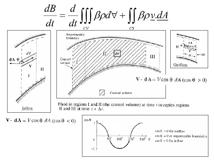
Reynolds Transport Theorem • A method for applying physical laws to fluid systems flowing through a control volume • B = Extensive property (quantity depends on amount of mass) • b = Intensive property (B per unit mass) Total rate of change of B in fluid system (single phase) Rate of change of B stored within the Control Volume Outflow of B across the Control Surface
Mass, Momentum Energy Mass Momentum B m mv b = d. B/dm 1 v d. B/dt 0 Physical Law Energy Newton’s Conservation First Law of Second Law of of mass Thermodynamics Motion
Reynolds Transport Theorem Total rate of change of B in the fluid system Rate of change of B stored in the control volume Net outflow of B across the control surface
Continuity Equation B = m; b = d. B/dm = dm/dm = 1; d. B/dt = 0 (conservation of mass) r = constant for water hence or
Continuity equation for a watershed I(t) (Precip) Hydrologic systems are nearly always open systems, which means that it is difficult to do material balances on them What time period do we choose to do material balances for? d. S/dt = I(t) – Q(t) Closed system if Q(t) (Streamflow)
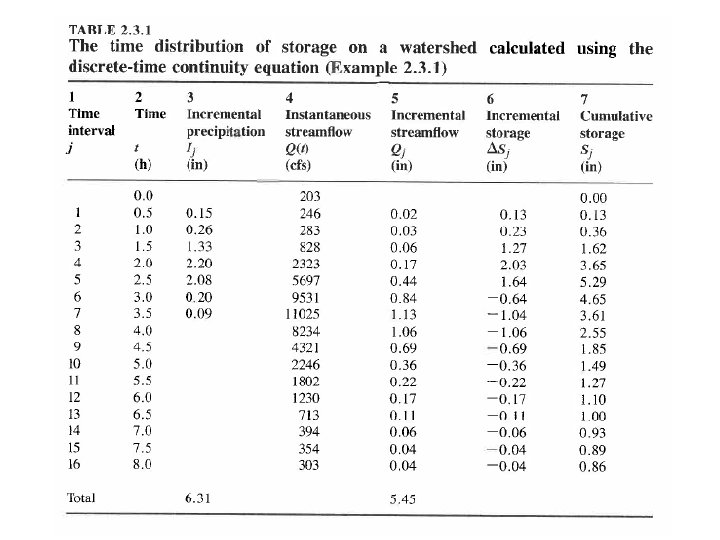
Continuous and Discrete time data Figure 2. 3. 1, p. 28 Applied Hydrology Continuous time representation Dt j-1 j Sampled or Instantaneous data (streamflow) truthful for rate, volume is interpolated Can we close a discrete-time water balance? Pulse or Interval data (precipitation) truthful for depth, rate is interpolated
Ij Continuity Equation, d. S/dt = I – Q applied in a discrete time interval [(j-1)Dt, j. Dt] Qj Dt DSj = Ij - Qj j-1 Sj = Sj-1 + DSj j