CATHODIC PROTECTION 5 1 INTRODUCTION Cathodic protection is


 Galvanic cell A galvanic cell is formed when two metals differing in potential")


 Disadvantages 1. It has limited applications compared to impressed current. 2. Driving voltage")
 Advantages")


- Slides: 60
CATHODIC PROTECTION 5, 1 INTRODUCTION Cathodic protection is a proven corrosion control method for protection of underground and undersea metallic structures, such as oil and gas pipelines, cables, utility lines and structural foundations. Cathodic protection is now widely applied in the protection of oil drilling platforms, dockyards, jetties, ships, submarines, condenser tubes in heat exchangers, bridges and decks, civil and military aircraft and ground transportation systems.
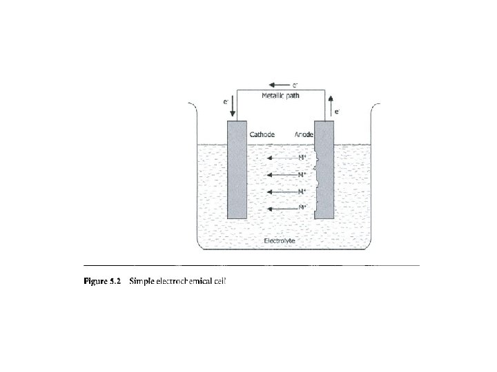
Corrosion current flows between the local action anodes and cathodes due to the existence of a potential difference between the two (Fig. 5. 1). As shown in Fig. 5. 2, electrons released in an anodic reaction are consumed in the cathodic reaction. If we supply additional electrons to a metallic structure, more electrons would be available for a cathodic reaction which would cause the rate of cathodic reaction to increase and that of anodic reaction to decrease, which would eventually minimize or eliminate corrosion.
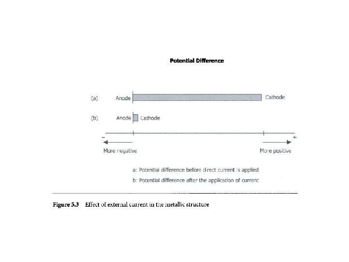
5. 2 BASIS OF CATHODIC PROTECTION Figure 5. 3 illustrates the simple principle of cathodic protection. On application of an external current, the difference of potential between the cathodes and anodes on the structure decreases. Corrosion stops when potential of cathode becomes equal to the potential of anode. The anode would become more negative and the cathode more positive. Cathodic protection is, therefore, achieved by supplying an external negative current to the corroding metal to make the surface acquire the same potential to eliminate the anodic areas. The anodic areas are eliminated by transfer of electrons. After a sufficient current flow, the potential of anodic areas would become negative enough for corrosion to stop. (a) There must be an anode, a cathode, an electrolyte and a metallic path for the transfer of electrons. (b) A source of DC current to supply electrons. (c) Sufficient direct current should be applied to eliminate the potential difference between the anode and the cathode.
5. 3 WORKING OF CATHODIC PROTECTION SYSTEM Figures 5. 4 a and b show how, in principle, a cathodic protection system works. Figure 5. 4 a shows a buried pipeline with anodic and cathodic areas prior to the application of the cathodic current. Figure 5. 4 b shows the same pipeline after the cathodic protection.
the metallic path. Structures, such as pipelines buried in the ground are affected by the presence of concentration cells, galvanic cells and stray currents. Some typical cells are described below. (a) Concentration cell A concentration cell is formed by the differences in concentration of salts, degree of aeration, soil resistivity and degree of stress to which the metals are subjected.
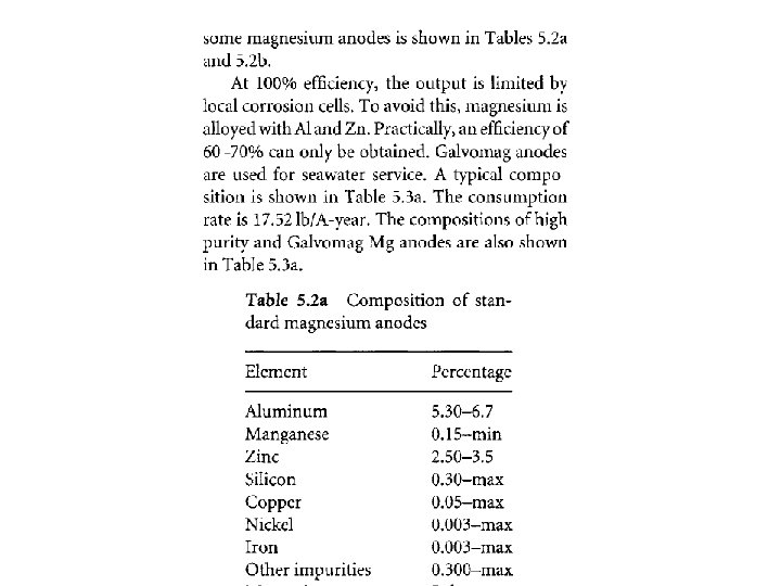
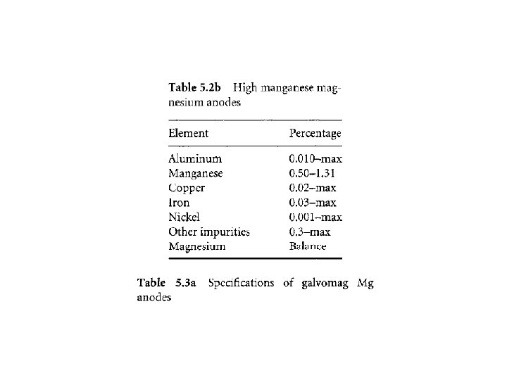
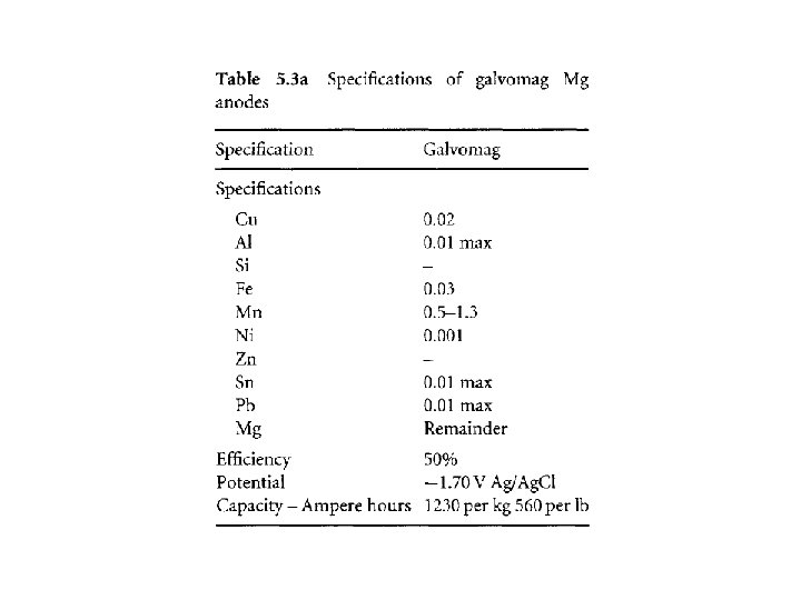
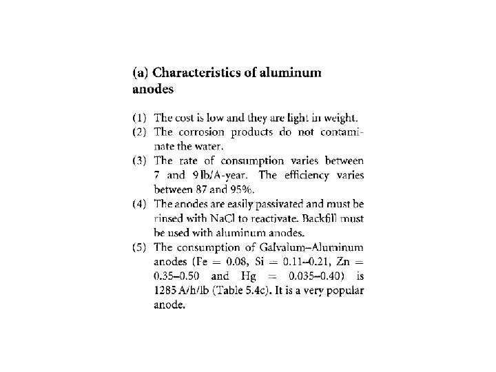
(b) Galvanic cell A galvanic cell is formed when two metals differing in potential are joined together. 5. 8 CATHODIC PROTECTION SYSTEMS Two types of cathodic protection systems exist: (a) Galvanic anode system or Sacrificial anode system. (b) Impressed current anode system. In the galvanic or impressed current system, the metallic structure is made the cathode (negative) by connecting it to galvanic anodes, which are more negative than the metallic structure to be protected. In this system, the current is generated by the corrosion of active metals, such as magnesium, zinc and also aluminum, which are
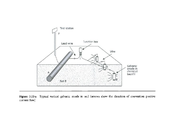
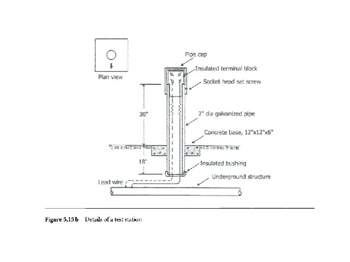
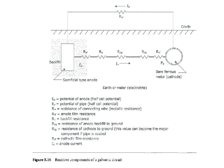
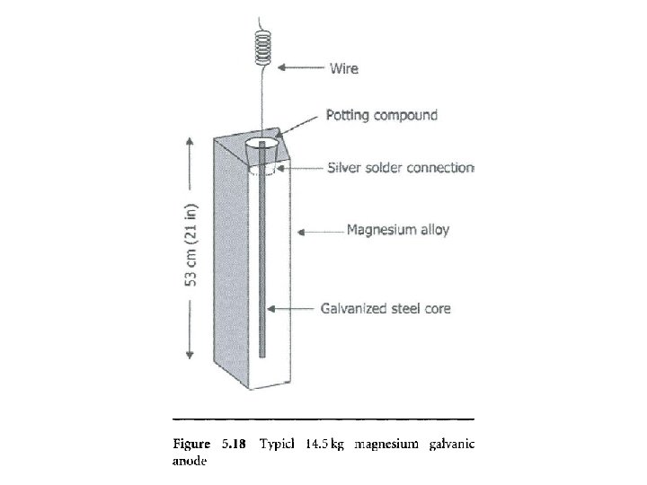
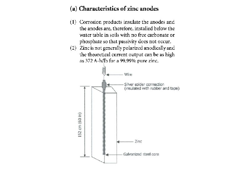
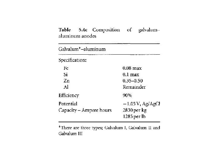
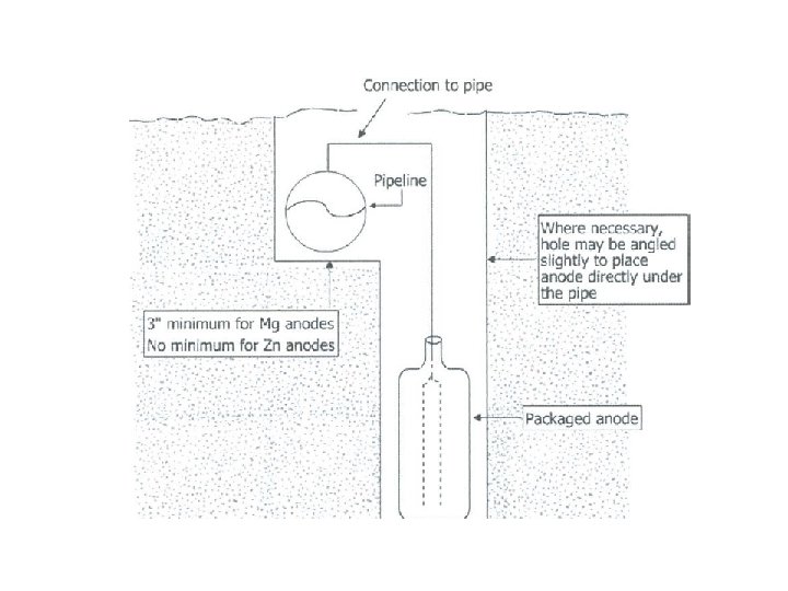
galvanic anodes: Al -> Al+ + 3 e Mg -> Mg++ + 2 e Zn -> Zn++ + 2 e The anodes of the above materials are utilized as sources of electrons which are released when the anodes are buried in the soil corrode. The electrons released pass through the metallic connection between anode and steel, and thus enter the structure to be protected. A suitable anode is buried adjacent to and level with the invert (lowest part) of a pipeline. A connection is made between the anode and the pipeline. The anode, generally magnesium or zinc, is connected to the pipeline or any buried metallic structure by an insulated cable. A schematic diagram of a galvanic anode cathodic protection system is shown in Fig. 5. 15 a. The figure shows a carbon steel pipe (A), magnesium anode (B), chemical backfill (C) surrounding the anode, wires connecting the carbon steel pipe to the anode, the soil (E) and test station (F). The details of test station are shown in Fig. 5. 15 b. The resistive component of a galvanic circuit is shown in Fig. 5. 16.
The anodic installation is often designed for ten years but may last much longer if current demand is low. The following are the advantages and the disadvantages of the galvanic anode system: (a) Advantages 1. It requires no external source, which might fail. 2. It is economical. 3. It can be easily installed. 4. It can be easily maintained. 5. It can be used in areas where the soil resistivity is low. 6. Lesser interference with the other metallic structures is caused because of a relatively low current output. 7. The current is evenly distributed,
(b) Disadvantages 1. It has limited applications compared to impressed current. 2. Driving voltage is fixed and cannot be manipulated, except by selecting Mg instead of Zn for example. 3. The cost of protection is high for bare systems (uncoated structures). 4. As no above-ground equipment is used, it is difficult to trace the protected system, unless contact posts are provided.
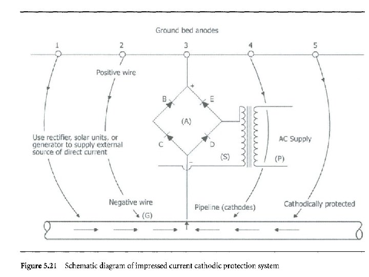
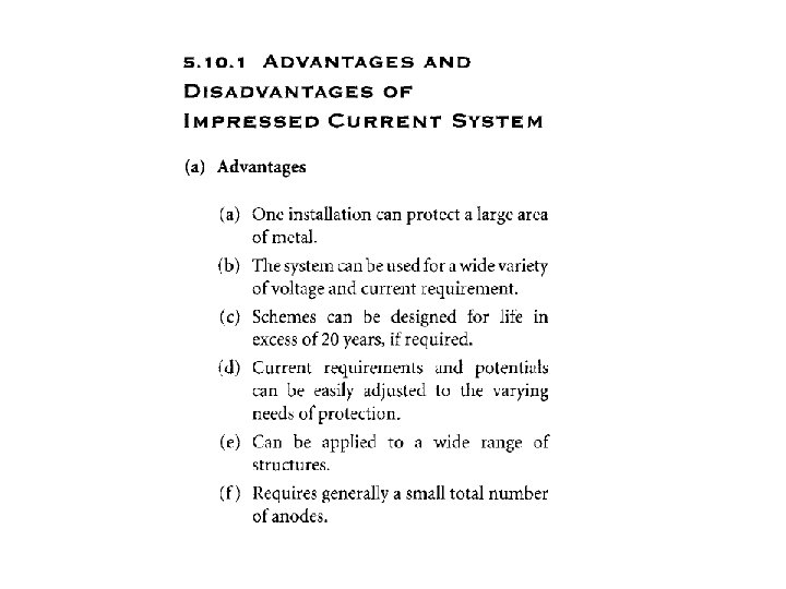
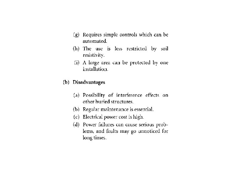
The following are the advantages and disadvantages of impressed current anode systems: (a) Advantages 1. Rectifiers available in unlimited current output. 2. May be designed for long lives. 3. More economical. 4. Possibility of variation of current to suit the changes in the system. (b) Disadvantages 1. External power is essential. 2. More complicated system for installation. 3. Less economical for smaller jobs. 4. Limited to use below a soil resistivity of 3000 ohms-cm.
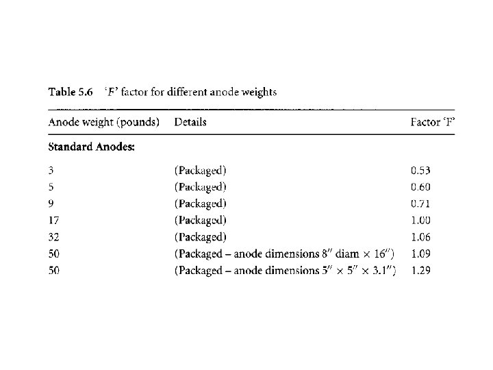
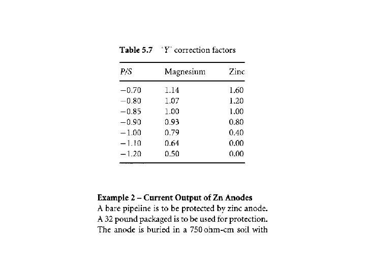
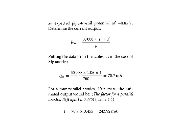
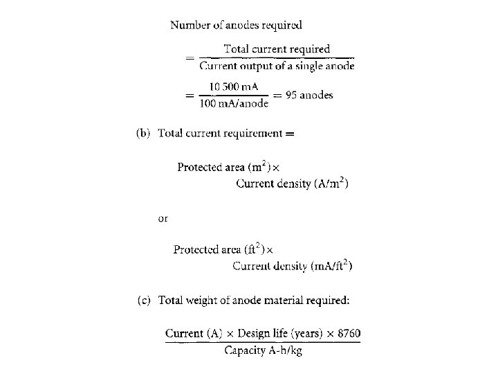
CALCULATIONS OF NUMBER OF ANODES REQUIRED AND SPACING The number of anodes required for a pipe or any bare structure can be conveniently estimated as per example given below. Suppose 10 000 ft of a bare 4 inch pipeline is to be protected and if the resistance of soil is 1000 ohms per cubic centimeter, the pipe requires 1 m. A/ft 2 for protection. The anode output curve shows 100 m. A per anode in this type of soil. The number of anodes can be easily calculated as shown below. Calculations (a) First calculate the area of the pipe: Area=(3. 14 x 4 x 10000)/12 = 10 500 f 2 Total current requirement = 10 500 x 1. 0 = 10 500 m. A
5. 11. 6 INSULATION AND ELECTRICAL CONTINUITY The structure to be protected must be free from all interconnected metal work in order to limit the flow of electric current on the structure. This is made possible by electrical insulation. 5. H. 7 INSULATION OF I N S U L A T I N G F L A N G ES Insulating flanges are installed to isolate the cathodically protected buried pipelines from above-ground pipelines. ISOLATION JOINT It is a flangeless factory assembled pipe-length which incorporates an insulating coupling. 5, 13 MAJOR IMPRESSED CURRENT ANODES The following are the major impressed current anodes:
s. 13. 1 HIGH SILICON CAST IRON Silicon iron anodes are composed of iron as the base metal with about 15% silicon and 1% carbon, additionally alloyed with chromium (5%), manganese (1%) and molybdenum (2%). The maximum current output is 50 A/m 2 and the rate of consumption is between 90 and 250 g/A/year. Anodes containing Mo are used in high-temperature media. A typical analysis of high silicon cast iron anode is shown below in Table 5. 8. It is generally used for onshore cathodic protection applications.
develops an adherent oxide layer of high electrical resistance. The oxide layer prevents corrosion by acting as a barrier. Titanium acts as an inert support for the platinum. 5. 13. 5 LEAD A N O D ES Lead anodes are made of various lead alloys, such as Pb-l. Ag 6 Sb and Pb-l. Ag-5 Sb-l. Sn. The density of a lead anode is around 11. 0 to 11. 2 g/cm 3. 5. 1 5 DESIGN PARAMETERS IN CATHODIC PROTECTION The basic design requirement for cathodic protection is the choice of current density per square foot or square meter of the surface area to be protected. The choice of current density can vary from something in the order of 100 m. A/ft 2 for a bare structure in water to as low as 0. 0001 m. A/ft 2 for well-coated pipes or
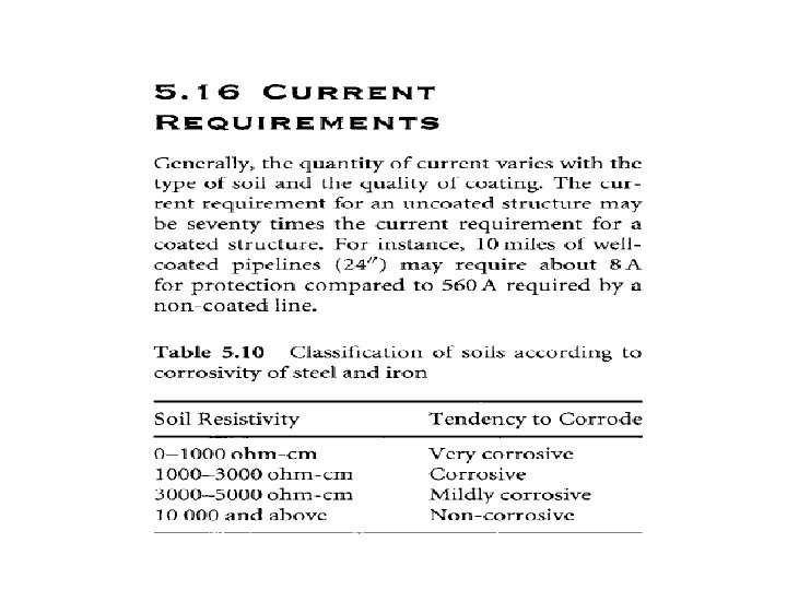
structures of high resistivity. To estimate the current requirements, knowledge of soil resistivity is of a primary importance. The following are the major characteristics of soils: (1) Sandy-type soils are less corrosive than nonhomogeneous soils. (2) Homogeneous soils are less corrosive than heterogeneous soils. (3) Well aerated soils are less corrosive than sparsely aerated soils. The more aerated soils tend to be brown in color. (4) Soils low in organic matter are less corrosive than soils with high amount of organic matter. (5) High acid and high alkaline soils (high p. H) are more corrosive. (6) Soils containing sulfate reducing bacteria are more corrosive than soils free from this bacteria. (7) Soils having low electrical resistivity are more corrosive than soils having high electrical resistivity. The soils can be classified as below with respect to the corrosivity of steel and iron (Table 5. 10).
Table 5. 10 Classification of soils according to corrosivity of steel and iron. Soil Resistivity Tendency to Corrode 0 -1000 ohm-cm Very corrosive 1000 -3000 ohm-cm Corrosive 3000 -5000 ohm-cm Mildly corrosive 10 000 and above Non-corrosive