Corrosion Control Corrosion Mitigation Cathodic Protection Regulatory requirements


- Slides: 29

Corrosion Control – Corrosion Mitigation & Cathodic Protection Regulatory requirements

Presented By Thomas Finch NACE Senior Corrosion Technologist

� Corrosion Troubleshooting � Cathodic Protection Tools and Equipment � Establishing Test Stations, and the Difference Between Test Points and Test Stations � Monitoring Requirements

� This seminar will cover only external corrosion as it applies to pipeline systems. � We will be discussing The Code of Federal Regulations, CFR 49, Part 192, as it applies to hazardous materials pipelines. � For specific regulations for your industry, refer to any specific codes or statutes. � The materials in this course may be downloaded to the Course site. Thank you!

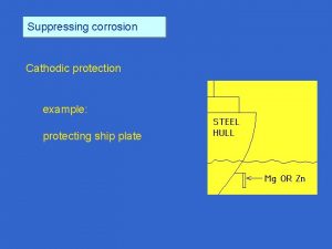
� Simply put, the objective of cathodic protection is to make all exposed external surfaces of the pipeline a cathode with respect to the basic corrosion cell � Two types of cathodic protection: ◦ Sacrificial anode, where a more reactive metal is connected to the pipeline, causing a galvanic corrosion cell where the anode is consumed, thus protecting the pipeline ◦ Impressed current, where an electrical device, called a rectifier and an impressed-current ground bed are connected to the pipe in a way that prevents corrosion

Anode Cathod e Anode Cathode Anode Cathod e Anode Cathode Cathode Before theapplicationof of. Cathodic. Protection After the Anode

� Sacrificial Anode Cathodic Protection � Impressed Current Cathodic Protection

About Sacrificial Anode s

About Impressed Cur rent

� Cathodic Protection can only be effective if the pipeline is in a common electrolyte with the cathodic protection system � Examples where CP may not be effective: ◦ ◦ Atmospheric Corrosion Internal corrosion Pipe in congested pipeline corridors Electrical shielding, such as pipe in a casing, or pipe encased in concrete, or near dense rock

Corrosion Troubleshooting Basics

� We ◦ ◦ will cover: CP Troubleshooting Equipment How to set up a cathodic protection area Determining the amount of CP Test Stations needed Electrical troubleshooting basics

� � � A good Digital Multimeter (DMM) A Copper-copper sulfate (Cu. SO 4) reference electrode (called a “half-cell”) Good quality Low frequency pipe/cable locator Various slide resistors (25, 50, 100 Watt) A high quality Current Interrupter Miscellaneous jumper leads with alligator-style clips at each end

� � Using a DMM and half-cell, remove the half-cell cap before taking the reading, and replace the cap after reading. In order to minimize IR drop error when taking P/S readings, you should always place the half-cell as close as possible to the tested structure. It is acceptable to pour a small amount of water where you will embed the half cell in earth. Use the VDC setting on the DMM, and insert the test leads into the appropriate ports to read DC volts. Place the black (-) lead onto the half-cell, and the red (+) lead onto the structure. Good metal contact must be made on the structure and half cell.

� In asking the general question, “How many test points will I need, to adequately monitor a cathodic protection area? ” the answer is not a simple one. � In CFR 49, § 192. 469 External corrosion control: Test stations, it states: “Each pipeline under cathodic protection required by this subpart must have sufficient test stations or other contact points for electrical measurement to determine the adequacy of cathodic protection. ” [Amdt. 192– 27, 41 FR 34606, Aug. 16, 1976]

� § 192. 471 External corrosion control: Test leads. ◦ (a) Each test lead wire must be connected to the pipeline so as to remain mechanically secure and electrically conductive. ◦ (b) Each test lead wire must be attached to the pipeline so as to minimize stress concentration on the pipe. ◦ (c) Each bared test lead wire and bared metallic area at point of connection to the pipeline must be coated with an electrical insulating material compatible with the pipe coating and the insulation on the wire.

� Using a DMM and half-cell perform a random P/S survey of the area. Determine if the system meets one or more CP criteria. The more common criteria include: -. 85 Vdc, 100 m. V shift, and 300 m. V shift. Less used are the E Log I and Net protective current criteria. � Use the procedures on the slides that follow to establish the number of test stations you will need. � For ease of illustration, we will use the -. 85 Vdc criterion.

� � � If the initial random P/S survey indicates that all readings meet the criterion, use a jumper lead with alligator clips, and short an insulator out. This may be located where the piping enters a building, or at a meter setting. Then take random P/S readings throughout the tested section. If the entire section of pipe drops below the criterion, you may only need one test station, however, we recommend you establish a minimum of two stations per section. If only a portion of the section drops below the selected criterion, continue to the point where the readings do not drop, and then short out the piping in the portion that was unaffected. Continue testing until you establish all test stations within the area.

� Example setup: of electrical testing for test station KNOWN INSULATOR UNKNOWN INSULATOR

� If your initial monitoring indicates that the criterion is not being met, then the steps become more complex, but not impossible. In this case, there may be: ◦ An electrical short on a meter or other aboveground pipeline component. Examples include a fence contacting a meter, house piping touching the meter riser, or a bad (shorted) insulator on the meter setting. ◦ A main-to-main or main-to-service underground contact. Examples include a water or sewer main touching a gas main or service line, or a CATV or satellite cable grounded to the riser. � These are not all situations that may cause the cathodic protection system to become unsuccessful at protecting the pipeline.

� � � You will have to locate and clear all insulator shorts and contacts before performing electrical tests to determine the number of test points needed. You must use a pipe locator to accomplish this. A pipe or cable locator is a two-part electrical device that sends an electric signal down the pipeline using the transmitter, and then detects this signal through the receiver to locate electrical shorts and contacts. You must use conductive locating, not inductive locating, to perform this task.

� � � The objective of line locating is that, rather than locating the pipeline, you are searching for any metal objects that may contact the pipeline, as well as any dielectric unions that are not working. As in the previous illustration, conductive locating only energizes the line it is attached to, and/or the main line. Other foreign lines are not normally picked up. This is largely due to the fact that electricity always follows the path of least resistance, and that is normally down the main line. If you pick up a service line or other unknown line, and the signal strength or tone increases, then you have most likely found an electrical short or contact. Repair or replace the insulator, or clear the contact, Once all contacts or electrical shorts are cleared, then the next step is to perform a simple current requirement test.

Begin by locating a suitable test location within the section to be tested. Suitable conditions include ready access to the pipeline at a meter or other aboveground piping; a metal structure for use as a temporary ground bed, such as a metal post, barricade, anode connection or short section of fence. Connect the DC positive post of a truck battery or other DC power source to a temporary ground. Connect the DC negative post to the pipeline. Then perform pipe-to-soil testing within the section, recording P/S potentials found, and the location, etc. CP Area - - + DC power source Temporary Ground

Conduct a P/S survey: � Once you have cleared all contacts and electrical insulator shorts and you have set up the simple current requirement test, take P/S readings throughout your affected area. � If the P/S testing indicates that the entire section now meets the selected criterion, then you may only need one test point within the section, however, as in the previous situation, we recommend you establish a minimum of two test stations within each section. � If P/S tests indicate only a portion of the section now meets the selected criterion, then you must relocate your DC power source to the unaffected area, and reapply current, retesting P/S once again, until you have established all test station in the section. CP Area UNKNOWN INSULATOR - - + UNKNOWN INSULATOR DC power source

�A test point is any aboveground access point where pipe-to-soil testing may be performed. It can be an isolation point, a meter, a regulator set, etc. � A test station may be an assigned test point or a specific test lead wire attached to underground piping, and is used for annual testing � You must always read your test stations annually, but you should read random test points as well, throughout your area, just to verify the test stations you currently have are still valid.

We Have covered: � The Basic Corrosion Cell � Forms of Corrosion � Three Tools to Fight Corrosion � Cathodic Protection and its Limitations � Corrosion Troubleshooting � CP Tools and Equipment � Establishing Test Stations, and the Difference Between Test Points and Test Stations

Advanced CP Fundamentals

A ny Question s?

Thank You! END
 Cathodic protection presentation
 Cathodic protection monitoring system
 Passive cathodic protection
 Zinc ribbon ac mitigation installation
 Dry corrosion and wet corrosion
 Difference between wet corrosion and dry corrosion
 Anodic peak current
 Cathodic peak current
 Corrosion prevention casing filler
 Lemförder corrosion protection
 Missile launcher closed-loop system
 Corrosion control solutions
 Patrick bong
 Mold damage somerset
 Bad news mitigation
 Mitigation strategy examples
 Avoidance risk
 Nop sled buffer overflow
 Preparedness mitigation response recovery
 Mt st francis colorado springs
 The word mitigation has come to mean to
 Climate change mitigation
 Risk avoidance
 Halimbawa ng mitigasyon
 Water mitigation beaumont
 Colbert cameron mitigation bank
 Structural mitigation
 Ransomware mitigation strategies
 Flood mitigation assistance program
 Risk mitigation assessment
