AnNajah National University Engineering College Civil Engineering Department


 Project Description Al- Emara building lies in Rafedia Village - Number of stories")
 Site and Geology The structure will be built on a hard stone layer")
 Materials ØConcrete : fc=(32 MPa)for columns and shear walls fc=( 28 MPa) for")
 Loading q Gravity loads • Dead load : consists of own weight of")

 Final Dimensions :")
 Verification of SAP Model ØCompatibility Check")


 For the column")


 from sap in the x-direction = 1.")

 from sap in the y-direction = 1.")
 Seismic zone factor")
Soil factor Soil type =SB")
''R'' factor R = 3. 5 ( ordinary moment - resisting frame )")
Importance factor ''I'' For residential and commercial building importance factor ''I'' = 1 5)")
 Function Input")
 Load Cases in x-direction")

Base Shear :")
 Design for Columns For static design the percent of steel for all columns")
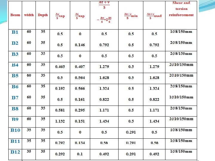
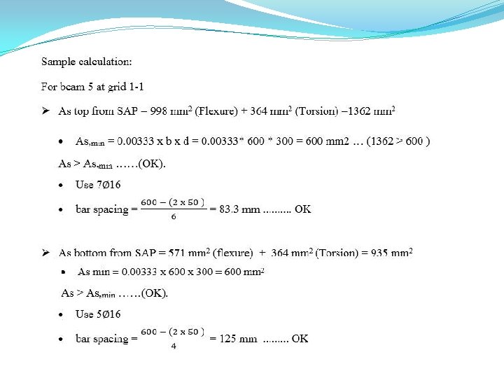
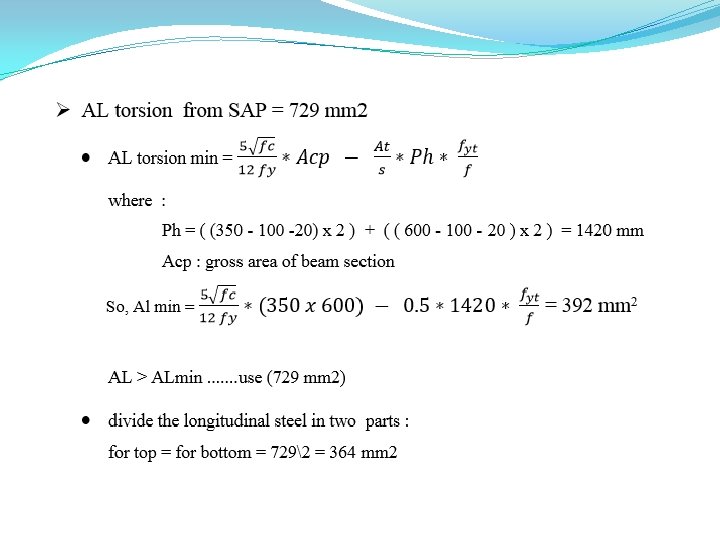
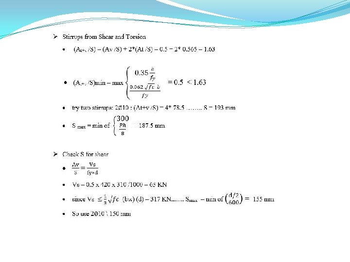
 Design for beams")
 Design of Shear walls The following table shows the reinforcement of shear walls:")


- Slides: 74
An-Najah National University Engineering College Civil Engineering Department Graduation Project Structural Design of Al-Emara building Under supervision of: Dr. Wael Abu. Assab
Outline
Chapter 1 : Introduction
1) Project Description Al- Emara building lies in Rafedia Village - Number of stories = 16 - Building height = 55 meter The following table shows floors of building with own function and net area Function Net Area(m 2) Floors Basement 1 Garages 615. 8 Basement 2 Garages 615. 8 Ground Storage 615. 8 1 st & 2 nd Offices & Storage 615. 8 3 rd - 16 th Residential 397. 8
2) Site and Geology The structure will be built on a hard stone layer which has a bearing capacity 350 KN/m 2. 3) Codes and standards ● ACI 318 -08: American Concrete Institute provisions for reinforced concrete structural q design ● IBC-2009: International Building Code ● ASCE 7 -05: American Society of Civil Engineers
4) Materials ØConcrete : fc=(32 MPa)for columns and shear walls fc=( 28 MPa) for others ØReinforcing Steel: The yield strength of steel is equal to (420 MPa). ØOthers : Material γ(KN/m 3) Reinforced concrete 25 Plain concrete (mortar & plastering 23 Aggregate 18 Blocks 12 Masonry stone 27 Tile 25
5) Loading q Gravity loads • Dead load : consists of own weight of the structural elements. • Superimposed dead load = 4 KN/m 2 • Wall weight =21 KN/m q Lateral loads Mainly Earthquake which will be discussed in dynamic design
Chapter Two : Static Design
1) Final Dimensions :
2) Verification of SAP Model ØCompatibility Check
ØEquilibrium Check
ØStress Strain Check q Stress Strain Check for Slab moment :
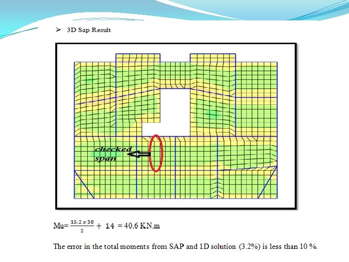
3 - Design of Slab 1 - Check for shear ü Hand Calculation : üSap Result
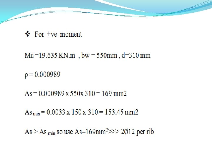
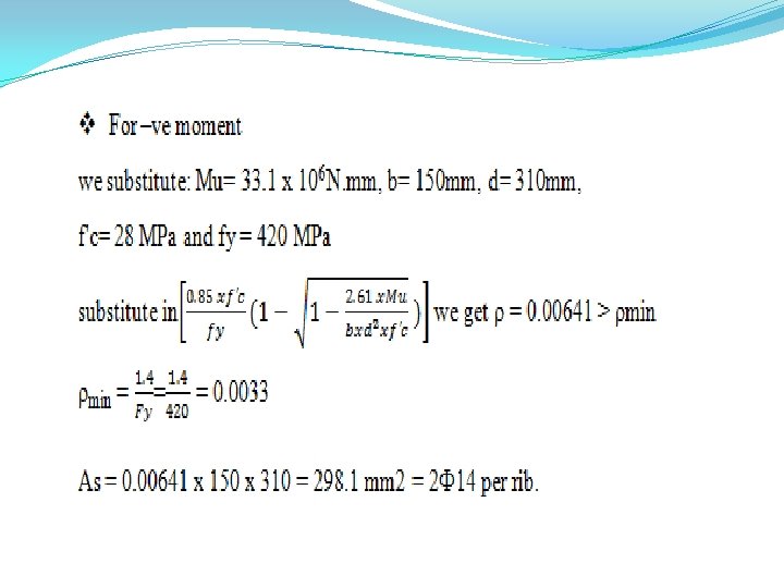
2 - Design for Bending Moment
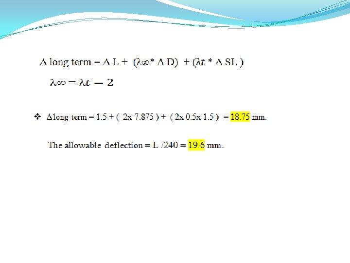
3 - Deflection check for slab - Actual beams deflection = total beam deflection - axial deformation • of near columns. • Actual floor deflection = total deflection - the avg. axial deformation of columns Actual slab deflection = Actual floor deflection - the avg. Actual • beams deflection
we are going to calculate the long term deflection then to be compared with allowable value , We take the maximum deflection obtained in the 15 th floor and The slab deflection is calculated as follow
4 - Design for Beams
5 - Design of Columns : C 1 Floor # dimension C 2 # of bars dimension C 3 # of bars # of dimension C 5 C 4 bars # of dimension bars dimension # of bars Base 2 - 800 x 300 12∅16 1000 x 300 16 c 16 1100 x 350 16∅18 3 - 6 600 x 300 9∅16 800 x 300 12∅16 950 x 300 12∅18 7 - 11 300 x 400 6∅16 500 x 300 8∅16 700 x 300 12∅16 12 - 14 300 x 200 6∅14 400 x 200 6∅14 500 x 200 8∅14 2 nd floor 18∅18 1300*400 22∅18 18∅16 1300 x 300 16∅18 800 x 300 12∅14 900 x 300 14∅14 600 x 200 8∅14 700 x 200 8∅14 1250 x 350 1100 x 300
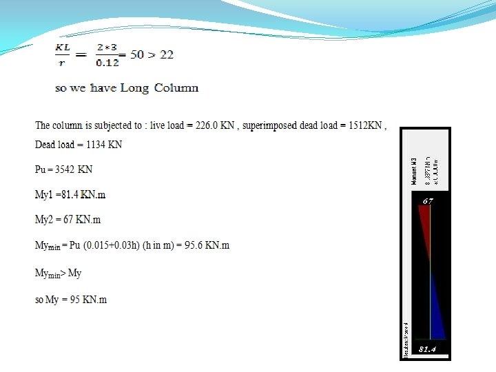
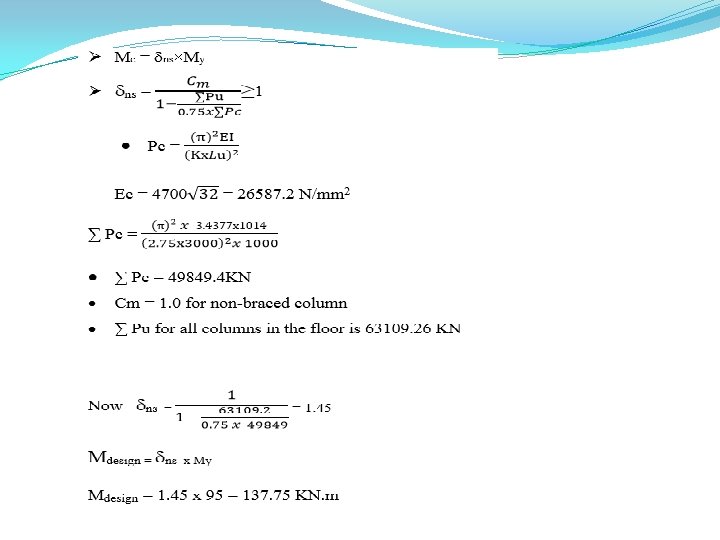
Check slenderness ratio for column C 5 at grid (4 -4) For the column in the basement one can be considered unbraced.
From the graph >ـــ K =2
See interaction diagram: From the figure ρ< 1% use minimum steel ratio ρ=1% As= 0. 01 *Ag = 0. 01 x 1300 x 300 = 3900 mm 2
Design of stirrups Use 2Ø 8 mm stirrups Vertical spacing between stirrups S ≤ 16 db: longitudinal bars S= 288 mm for db=18 mm. S ≤ 48 ds : for tie bar S=384 mm S ≤ least lateral dimension of column S=300 mm The spacing between stirrups is 280 mm for db=18 mm C 5
Design of footing
Deflection check �
Allowable stress check
Punching shear check for the critical column
Wide beam check �
Flexure design we selected a frame in the y-direction with width = 4 � m
Bending Moment diagram for the selected frame
Flexure reinforcement for the selected frame
We selected another frame in the x-direction
Bending Moment diagram for the selected frame
Flexure reinforcement for the selected frame
Design of stairs h min=�� /20=3. 35=0. 167 m⇒Use h=0. 20 m. Thickness of stair and threshold areas=0. 20 m,
Plan view of the stairs As shown, the stairs are surrounded by 3 shear walls which mean fixation from three sides.
3 D Model of the stairs for two stories.
Shear Check �
Bending moment diagram from SAP M+ = 18. 1 KN. m M - = 14. 1 KN. m
Flexural reinforcement Take max Mu = 18. 16 KN. m ρ = 0. 0015 As = ρ x b xd= 0. 0015 x 1000 x 180 = 268. 22 mm 2 Asmin = 0. 0018 x b x h=0. 0018 x 1000 x 200 = 360 > 268. 22 mm 2 Use Asmin= 360 (4ϕ 12/m) (bottom) and (top ).
Chapter Four : Dynamic Design
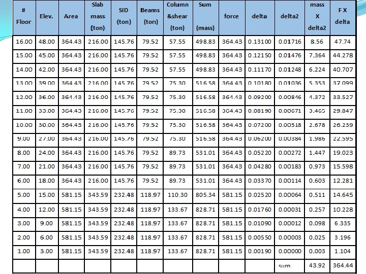
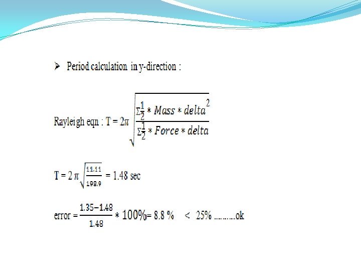
a- Dynamic Analysis We are going to analyze the building for modal response and compare the results between manual (Rayleigh method) and SAP program.
v. In x-direction : Ø Period (T) from sap in the x-direction = 1. 97 sec
Manual calculation "Rayleigh method"
v. In y-direction : Ø Period (T) from sap in the y-direction = 1. 35 sec
b- Design using Response spectrum according to UBC 97 Code 1) Seismic zone factor '' Z '' For Nablus city (Zone 2 B) Z= 0. 2
2)Soil factor Soil type =SB
3)''R'' factor R = 3. 5 ( ordinary moment - resisting frame )
4)Importance factor ''I'' For residential and commercial building importance factor ''I'' = 1 5) Acceleration seismic coefficient '' Ca '‘=0. 2 6) Velocity seismic coefficient '' Cv “=0. 2
7) Function Input
8) Load Cases in x-direction
In –y-direction
9)Base Shear :
10) Design for Columns For static design the percent of steel for all columns equal 1% after earthquake load the percent of steel remain 1% so the static design is OK for all columns 11) Design of slabs We found that the area of steel for gravity loads and the lateral steel is the same.
12) Design for beams
13) Design of Shear walls The following table shows the reinforcement of shear walls:
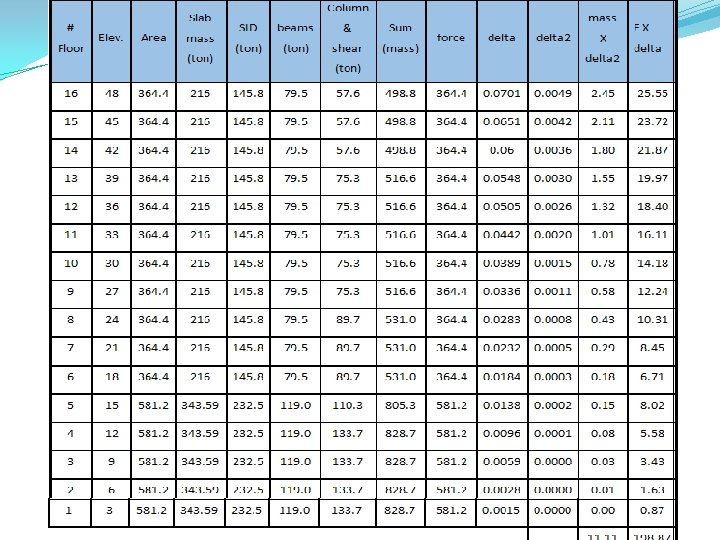
üHand Calculation for Shear wall 1 Once shear wall is analyzed, 5 internal ultimate forces can be computed; namely, P, Vx, Vy, Mx and My
1 - Check Shear in X-direction: 2 - Design Shear in Y-direction Vuy = 2026 KN needed stirrup : 1Ø 12 / 250 mm
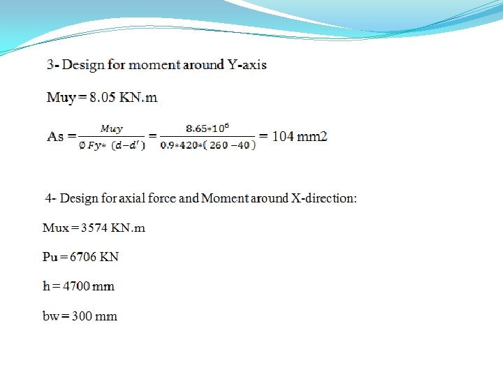
To find interaction diagram for this shear, wall simple 3 -D model was made by Sap 2000 program and we assumed area of steel to be As = 0. 0025 * 4700 * 300 = 3525 mm 2
Since he point is inside the interaction diagram so the area of steel provided is enough Total area of steel needed for axial load and moment = 3525 mm 2 +(2*104) mm 2= 3733 mm 2. . . . (25Ø 14)