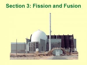
A2 Induced Fission 0 Introduction Generalities Liquiddrop picture


- Slides: 20

A-2 Induced Fission – 0 Introduction • Generalities • Liquid-drop picture • Chain reactions • Mass distribution • Fission barrier • Double fission barrier • After the scission point • Time scale in fission • Neutron-induced fission • Energy dependence of (n, f) cross sections • Neutron energy spectra • Nuclear reactors • Nuclear energy • A reactor fundamental research

A-2 Induced Fission – 1 Generalities Nuclear fission Decay process in which an unstable nucleus splits into two fragments of comparable mass. 1932: discovery of neutrons 1939: official discovery by Otto Hahn and Fritz Strassmann fission of 235 U Lise Meitner! (109 Mn) 1942: first “chain reacting pile” (E. Fermi) 1945: first nuclear explosion in Alamogordo (New Mexico, USA) 1972: discovery of Oklo (Gabon): unique natural nuclear reactor (1. 8 106 y ago) very abnormal isotopic ratios of 235 U/238 U in uranium ores

A-2 Induced Fission – 2 Liquid-drop picture Fission can be qualitatively understood on the basis of the liquid-drop model electrical repulsion pushes the 2 lobes apart fission fragment n n n 235 U high excitation and strong oscillation formation of a neck Note: fission liberates about 200 Me. V per atom! n fission fragment

A-2 Induced Fission – 3 Chain reactions If at least one neutron from each fission strikes another 235 U nucleus and initiates fission, then the chain reaction is sustained. If the reaction will sustain itself, it is said to be "critical", and the mass of 235 U required to produced the critical condition is said to be a "critical mass". A critical chain reaction can be achieved at low concentrations of 235 U if the neutrons from fission are moderated in water to lower their speed, since the probability for fission with slow neutrons is greater. A fission chain reaction produces intermediate mass fragments which are highly radioactive and produce further energy by their radioactive decay. Some of them produce neutrons, called delayed neutrons, which contribute to the fission chain reaction.

A-2 Induced Fission – 4 Mass distribution When 235 U undergoes fission, the average of the fragment mass is about 118, but very few fragments near that average are found. It is much more probable to break up into unequal fragments, and the most probable fragment masses are around mass 95 and 137. Most of these fission fragments are highly unstable, and some of them such as 137 Cs and 90 Sr are extremely dangerous when released to the environment. 235 U + n 236 U* 140 Xe + T 1/2 = 14 s b 140 Cs 64 s b 140 Ba 13 d b 140 La 40 h b 140 Ca 94 Sr + b 75 s 94 Y b 19 m 94 Zr 2 n

A-2 Induced Fission – 5 Mass distribution

A-2 Induced Fission – 6 Fission barrier U Fission occurs if there is an excitation energy greater than UB or an appreciable probability for tunneling through the potential energy barrier UB 1/r electric potential energy Spontaneous fission occurs via a quantum mechanical tunneling through the fission barrier. Fissibility parameter: x = Z 2/A range of the nuclear force r 0 r Spontaneous fission is possible only for elements with A 230 and x 45. Ground states spontaneous fission half-lives for (9. 8 2. 8) x 1018 y 238 U: (8. 2 0. 1) x 1015 y 235 U: 238 Pu: (4. 70 0. 08) x 1010 y 254 Cf: 60. 7 y 256 Fm: 2. 86 h 260 106 Sg: 7. 2 ms

A-2 Induced Fission – 7 Double fission barrier 50’s: enhancement in the study of the nuclear deformations for stable nuclei in between shell closures. the spherical shell model is unable to explain the large quadrupolar moments of nuclei at 150 < A < 190 and A > 220 ® unified model of A. Bohr and B. Mottelson: macroscopic + individual aspects 1955: S. G. Nilsson develops a deformed shell model the potential is defined by oscillation frequencies, functions of deformation parameters if the nucleus is deformed, the degeneracy of the energy levels of the spherical potential is partially lifted the spreading in energy of these levels increase with the deformation for small deformations, this spreading leads to an uniform repartition of the levels for large deformations, on can observe the appearance of shell effects due to the gatherings of Nilsson levels coming from different shells initially The presence of these level gatherings, because they lower the level density, is at the origin of the permanent deformation of some nuclei in their ground state. But, the total energy is overestimated for the high energies…

A-2 Induced Fission – 8 9 Double fission barrier The method proposed by Strutinski is the synthesis of the liquid drop model and the deformed shell model in order to describe simultaneously the mean value of the potential energy < Epot > and its local fluctuations as a function of the nucleon number and the nucleus deformation. macroscopic – microscopic model of fission Epot (Me. V) The oscillating aspects of the shell corrections in this model leads to the prediction of a fission barrier with two bumps: the double fission barrier. 230 Th 240 Pu 252 Cf 5 0 Bn deformation with Bn: binding energy of the neutron in the considered nucleus

A-2 Induced Fission – 9 Double fission barrier Experimental consequences hierarchy of the states of the fissioning nucleus as a function of deformation: ® compound states of class I: normally deformed and very dense (level density D = 0. 1 -1 e. V) compound states of class II: superdeformed with a reduced excitation energy E* ~ 2 -3 Me. V with a smaller level density (D = 0. 05 -10 Ke. V) These states have comparable properties: their presence and coupling with tunnel effect through the intermediate barrier have allowed a coherent interpretation of numerous experimental results in disagreement with the predictions of the liquid drop model. E excited states spectroscopy g class II states class I states fission isomers spontaneous fission deformation

A-2 Induced Fission – 10 Double fission barrier Fission isomers ® lowest class II states ® de-excitation through: - fission (tunneling through the 2 nd barrier) - g emission after tunneling to the 1 st well through the 1 st barrier ® these “form isomers” have a greater deformation than the ground state in the 1 st well ® 1 st discovery in 1962 (Polikanov), ~ 30 isomers have been observed in the U-Bk region ® E* = Eg. s. + 2 -3 Me. V few tens of ps < T 1/2 < 14 ms ® one measures the variation with the incident energy of the ratio between the number of delayed fissions (coming from the isomer) and the number of prompt fissions A statistical model allows generally to extract the height of the second well and the shape of the second barrier.

A-2 Induced Fission – 11 After the scission point Beyond the barriers, the system evolves irreversibly towards the scission. This transition is very fast (few 10 -22 s). During the scission, the system gets a large amount of energy (~20 -30 Me. V) that is used as deformation energy of the fragments. Just after the scission, the fragments convert their Coulomb energy in translation kinetic energy. They reach then 90% of their final kinetic energy in 1. 3 10 -20 s. As soon as the distance between the two fragments is larger than the nuclear force range (~ 2. 5 10 -13 cm), they get a deformation energy that they convert rapidly in internal excitation energy (this conversion is done with a damping of the collective vibrations in ~ 10 -21 s). The prompt neutron emission is performed in 10 -14 s (the distance between fragments is then 2. 10 -8 cm). The g’s are emitted in a larger time length which can reach few ms. The formed fragments are unstable because too rich in neutrons. The delayed neutrons represent only 1% of the total neutron emission but they are of great importance for the reactivity of reactors.

A-2 Induced Fission – 12 Time scale in fission

A-2 Induced Fission – 13 Energies in 235 U thermal fission < prompt energy > fragment Ekin 169. 0 neutron emission 4. 8 g emission 7. 0 180. 8 < delayed energy > b- energy 6. 4 delayed neutron emission 0. 01 g emission 6. 2 n emission 10. 0 22. 61 < total energy > 203. 41 The total kinetic energy of the fragments increases with the mass and the charge of the fissioning nucleus as Z 2/A 1/3. In the contrary, it is independent of the excitation energy of the fissioning system due to the effect of the Coulomb repulsion of the fragments formed at the scission.

A-2 Induced Fission – 14 Neutron-induced fission In the history of fission research, neutroninduced fission has always played the most important role (Hahn & Strassmann). Me. V The neutrons do not feel the Coulomb repulsion, only the nuclear attraction. Therefore nuclear reactions can be induced by neutrons of arbitrarily low energies. En < 0. 1 e. V L. E. Glendenin et al. , Phys. Rev. C (1981) 2600 The asymmetric fission is largely favoured. The light mass peak goes towards heavier fragments when the mass of the fissioning nucleus increases.

A-2 Induced Fission – 15 Energy dependence of (n, f) cross sections Case of 235 U and 237 Nb thermal neutrons 235 U: 237 Nb: neutron binding energy > maximum fission barrier large cross section neutron binding energy < maximum fission barrier small cross section when excitation energy E* > maximum fission barrier sharp rise of sf

A-2 Induced Fission – 16 Neutron energy spectra The most prominent neutron emission source is the evaporation from the fully accelerated fragments. 235 U(n, f) TM = 1. 352 Me. V <En> = 2. 028 Me. V B. E. Watt, Phys. Rev. 2 (1952) 1037 The integral neutron spectrum can be fitted with a Maxwellian distribution: With TM the only parameter characterizing the distribution. The average neutron energy is given by <En> = 3/2 TM.

A-2 Induced Fission – 17 Nuclear reactors It takes 1011 fissions per second to produce one watt of electrical power. As a result, about one gram of fuel is consumed per day per megawatt of electrical energy produced. This means that one gram of waste products is produced per megawatt per day, which includes 0. 5 grams of 239 Pu. Boiling Water Reactor Liquid-Metal Fast-Breeder Reactor Pressurized Water Reactor BWR: the most common in case of a leak the water can become radioactive PWR: the moderating and turbine waters are separated more expensive LMFBR: liquid sodium is used as moderator and heat transfer medium

A-2 Induced Fission – 18 Nuclear energy Electricity production in 2001 %

A-2 Induced Fission – 19 A reactor fundamental research Institute Laue-Langevin (Grenoble): a french-german-english lab
 Vapor pressure intermolecular forces
 The best coffee for the best you propaganda
 Emotional words propaganda
 Propaganda snob appeal
 Glittering generalities
 Bandwagon propaganda animal farm
 Glittering generalities persuasive technique
 Burger king propaganda technique used
 Propaganda techniques answer key grade 8
 Bandwagon advertising meaning
 Red herring propaganda definition
 Pinpointing the enemy examples
 Plain folks examples
 Glittering generalities advertising
 Glittering generalities definition
 Example of name calling
 Repetition propaganda meaning
 Card stacking commercials
 Glittering generality examples
 Define snob appeal
 Plain folks animal farm
