Wireless Communication Systems CS NCTU Lecture 14 FullDuplex

- Slides: 47
Wireless Communication Systems @CS. NCTU Lecture 14: Full-Duplex Communications Instructor: Kate Ching-Ju Lin (林靖茹) 1
Outline • What’s full-duplex • Self-Interference Cancellation • Full-duplex and Half-duplex Co-existence • Full-duplex relaying 2
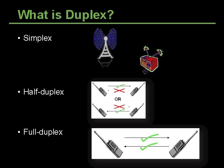
What is Duplex? • Simplex • Half-duplex • Full-duplex
How Half-duplex Works? • Time-division half-duplex • Frequency-devision half-duplex
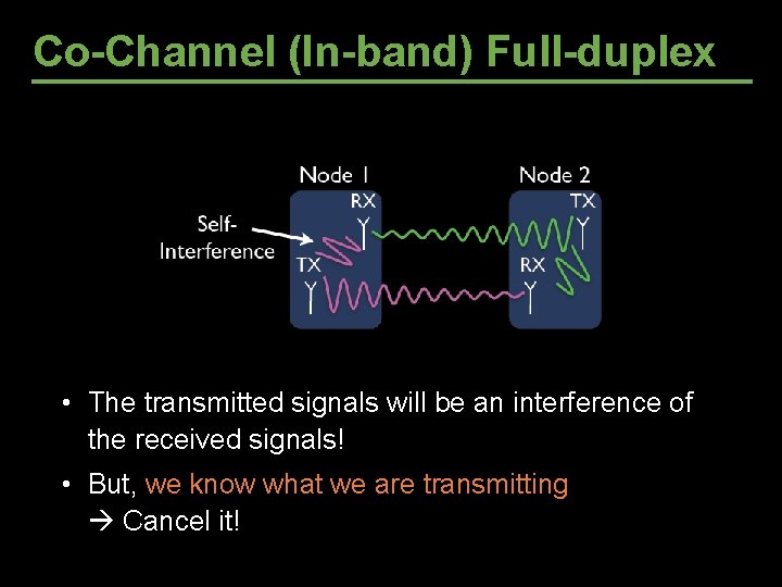
Co-Channel (In-band) Full-duplex Very strong self-interference (~70 d. B for 802. 11) • The transmitted signals will be an interference of the received signals! • But, we know what we are transmitting Cancel it!
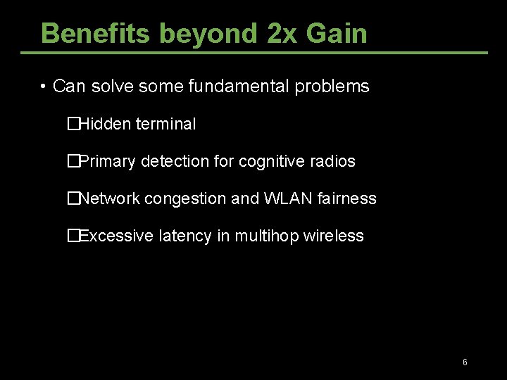
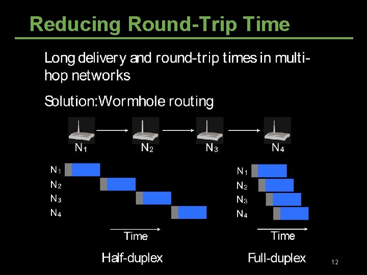
Benefits beyond 2 x Gain • Can solve some fundamental problems �Hidden terminal �Primary detection for cognitive radios �Network congestion and WLAN fairness �Excessive latency in multihop wireless 6
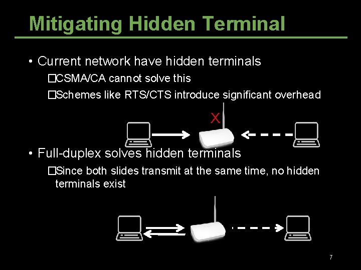
Mitigating Hidden Terminal • Current network have hidden terminals �CSMA/CA cannot solve this �Schemes like RTS/CTS introduce significant overhead X • Full-duplex solves hidden terminals �Since both slides transmit at the same time, no hidden terminals exist 7
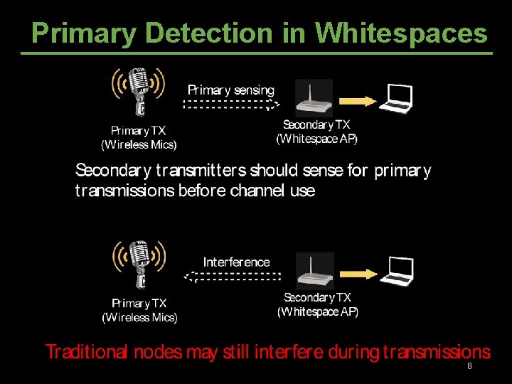
Primary Detection in Whitespaces 8
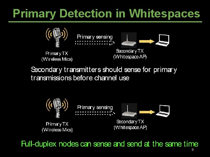
Primary Detection in Whitespaces 9
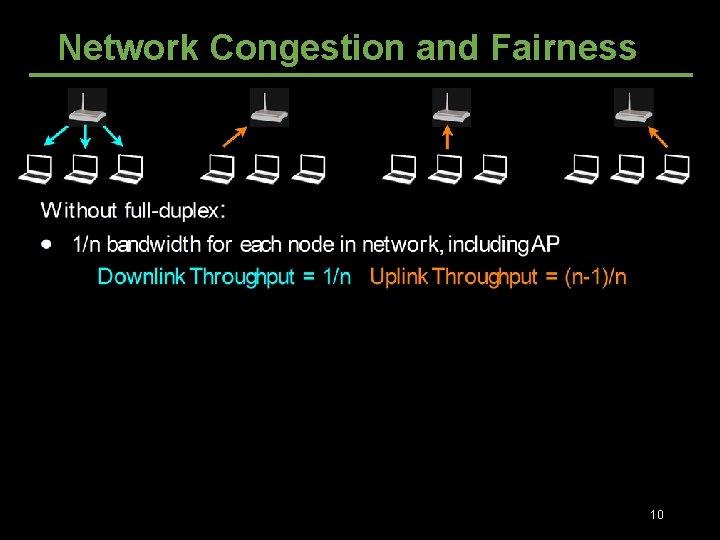
Network Congestion and Fairness 10
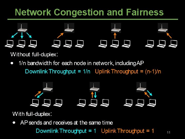
Network Congestion and Fairness 11
Reducing Round-Trip Time 12
Outline • What’s full-duplex • Self-Interference Cancellation • Full-duplex and Half-duplex Co-existence • Full-duplex relaying 13
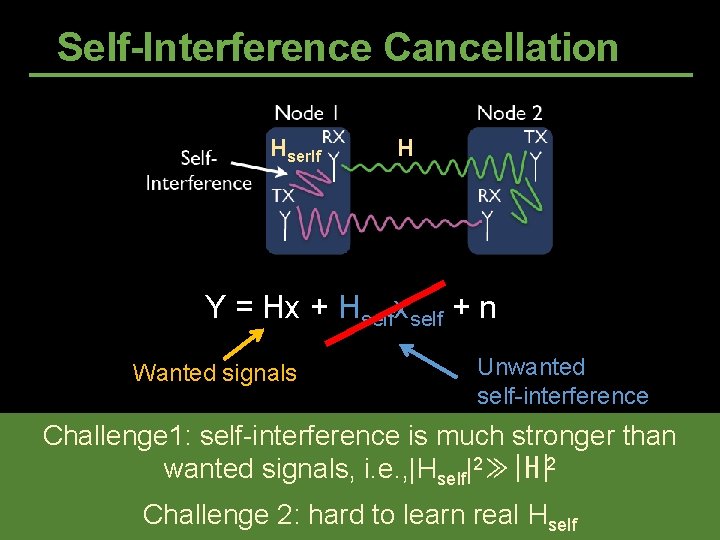
Self-Interference Cancellation Hserlf H Y = Hx + Hselfxself + n Wanted signals Unwanted self-interference Challenge 1: self-interference is much stronger than wanted signals, i. e. , |Hself|2≫|H|2 Challenge 2: hard to learn real Hself
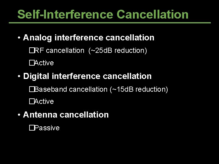
Self-Interference Cancellation • Analog interference cancellation �RF cancellation (~25 d. B reduction) �Active • Digital interference cancellation �Baseband cancellation (~15 d. B reduction) �Active • Antenna cancellation �Passive
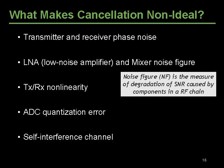
What Makes Cancellation Non-Ideal? • Transmitter and receiver phase noise • LNA (low-noise amplifier) and Mixer noise figure • Tx/Rx nonlinearity Noise figure (NF) is the measure of degradation of SNR caused by components in a RF chain • ADC quantization error • Self-interference channel 16
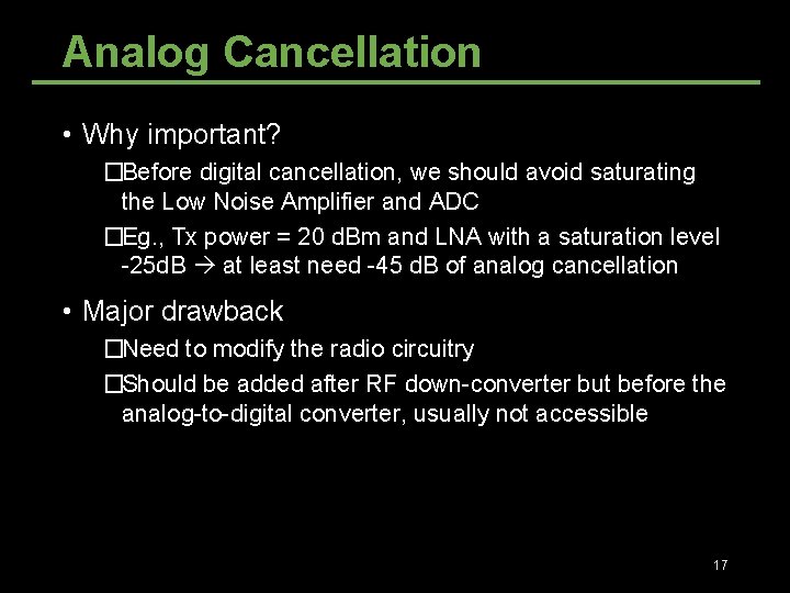
Analog Cancellation • Why important? �Before digital cancellation, we should avoid saturating the Low Noise Amplifier and ADC �Eg. , Tx power = 20 d. Bm and LNA with a saturation level -25 d. B at least need -45 d. B of analog cancellation • Major drawback �Need to modify the radio circuitry �Should be added after RF down-converter but before the analog-to-digital converter, usually not accessible 17
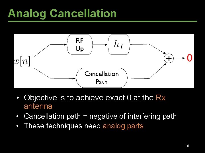
Analog Cancellation • Objective is to achieve exact 0 at the Rx antenna • Cancellation path = negative of interfering path • These techniques need analog parts 18
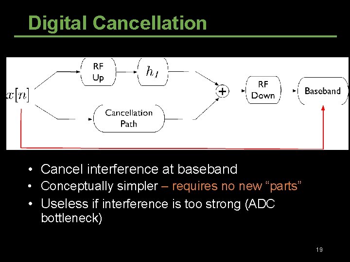
Digital Cancellation • Cancel interference at baseband • Conceptually simpler – requires no new “parts” • Useless if interference is too strong (ADC bottleneck) 19
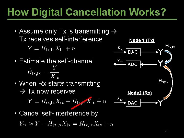
How Digital Cancellation Works? • Assume only Tx is transmitting Tx receives self-interference Xtx • Estimate the self-channel Ytx Node 1 (Tx) Htx, tx DAC ADC Hrx, tx • When Rx starts transmitting Tx now receives Node 2 (Rx) Xrx DAC • Cancel self-interference by 20
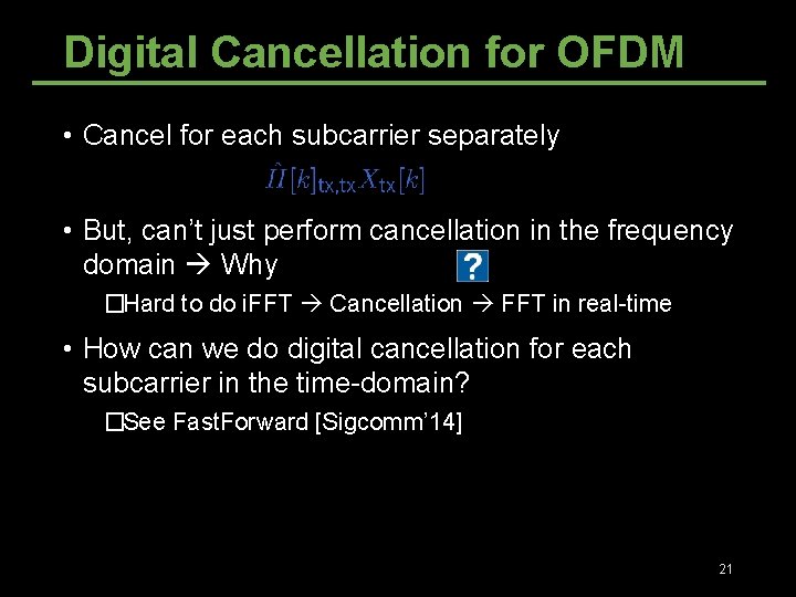
Digital Cancellation for OFDM • Cancel for each subcarrier separately • But, can’t just perform cancellation in the frequency domain Why �Hard to do i. FFT Cancellation FFT in real-time • How can we do digital cancellation for each subcarrier in the time-domain? �See Fast. Forward [Sigcomm’ 14] 21
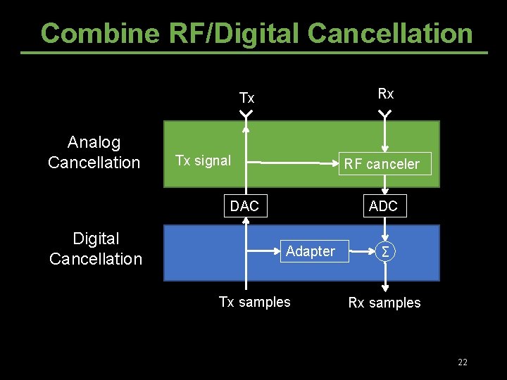
Combine RF/Digital Cancellation Rx Tx Analog Cancellation Tx signal RF canceler DAC Digital Cancellation ADC Adapter Tx samples Σ Rx samples 22
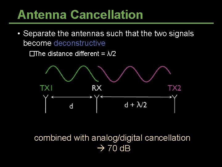
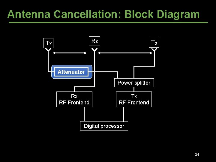
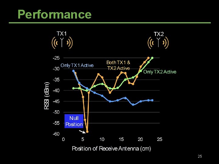
Antenna Cancellation • Separate the antennas such that the two signals become deconstructive �The distance different = λ/2 ~30 d. B self-interference cancellation combined with analog/digital cancellation 70 d. B
Antenna Cancellation: Block Diagram Rx Tx Tx Attenuator Power splitter Rx RF Frontend Tx RF Frontend Digital processor 24
Performance 25
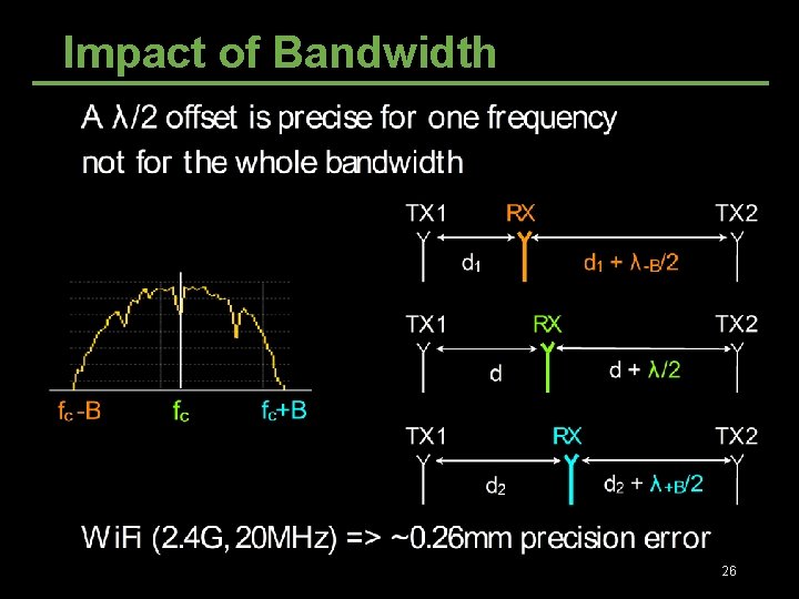
Impact of Bandwidth 26
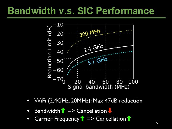
Bandwidth v. s. SIC Performance 27
Outline • What’s full-duplex • Self-Interference Cancellation • Full-duplex and Half-duplex Co-existence • Full-duplex relaying 28
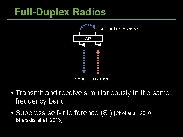
Full-Duplex Radios self interference AP send receive • Transmit and receive simultaneously in the same frequency band • Suppress self-interference (SI) [Choi et al. 2010, Bharadia et al. 2013]
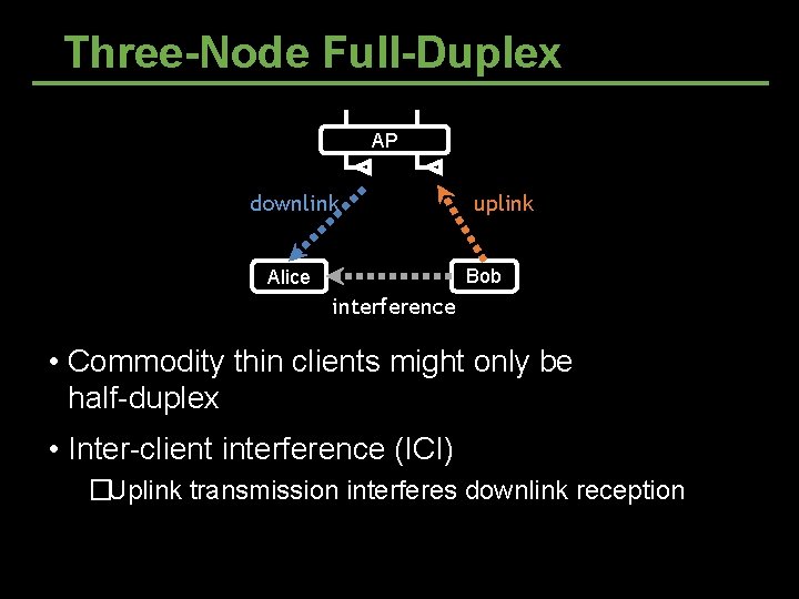
Three-Node Full-Duplex AP downlink uplink Bob Alice interference • Commodity thin clients might only be half-duplex • Inter-client interference (ICI) �Uplink transmission interferes downlink reception
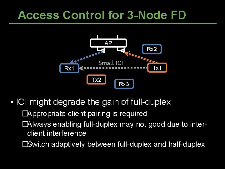
Access Control for 3 -Node FD AP Rx 1 Rx 2 Small ICI Tx 2 Tx 1 Rx 3 • ICI might degrade the gain of full-duplex �Appropriate client pairing is required �Always enabling full-duplex may not good due to interclient interference �Switch adaptively between full-duplex and half-duplex
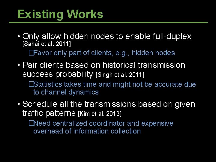
Existing Works • Only allow hidden nodes to enable full-duplex [Sahai et al. 2011] �Favor only part of clients, e. g. , hidden nodes • Pair clients based on historical transmission success probability [Singh et al. 2011] �Statistics takes time and might not be accurate due to channel dynamics • Schedule all the transmissions based on given traffic patterns [Kim et al. 2013] �Need centralized coordinator and expensive overhead of information collection
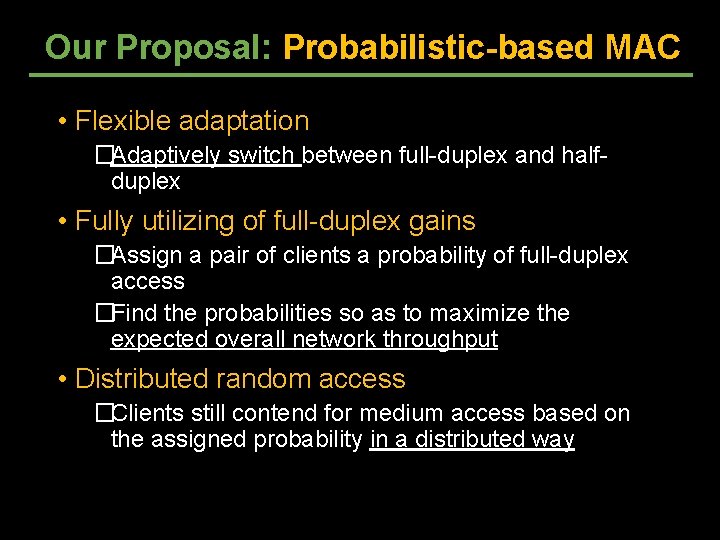
Our Proposal: Probabilistic-based MAC • Flexible adaptation �Adaptively switch between full-duplex and halfduplex • Fully utilizing of full-duplex gains �Assign a pair of clients a probability of full-duplex access �Find the probabilities so as to maximize the expected overall network throughput • Distributed random access �Clients still contend for medium access based on the assigned probability in a distributed way
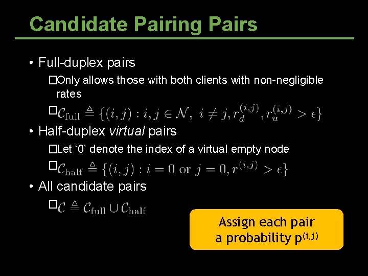
Candidate Pairing Pairs • Full-duplex pairs �Only allows those with both clients with non-negligible rates � • Half-duplex virtual pairs �Let ‘ 0’ denote the index of a virtual empty node � • All candidate pairs � Assign each pair a probability p(i, j)
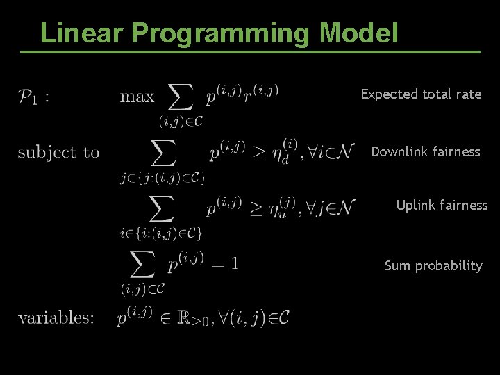
Linear Programming Model Expected total rate Downlink fairness Uplink fairness Sum probability
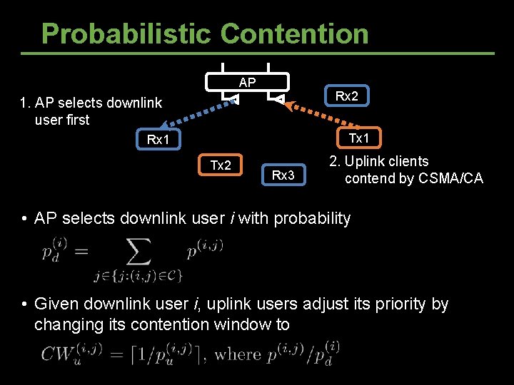
Probabilistic Contention AP Rx 2 1. AP selects downlink user first Tx 1 Rx 1 Tx 2 Rx 3 2. Uplink clients contend by CSMA/CA • AP selects downlink user i with probability • Given downlink user i, uplink users adjust its priority by changing its contention window to
Outline • What’s full-duplex • Self-Interference Cancellation • Full-duplex and Half-duplex Co-existence • Full-duplex relaying 37
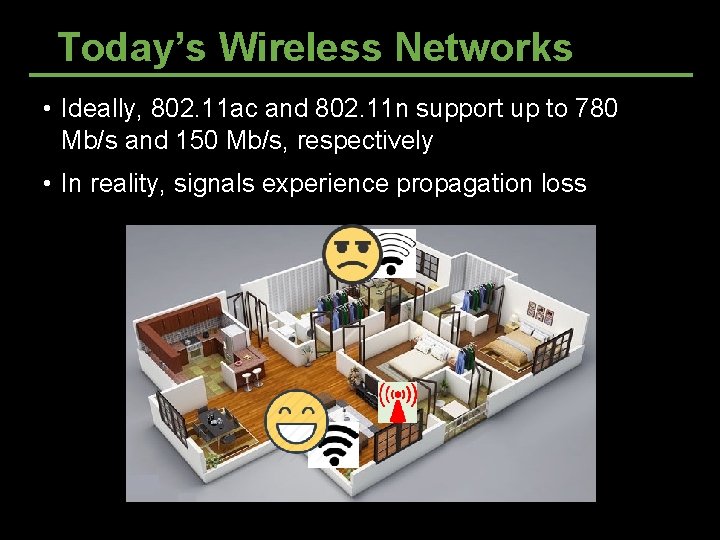
Today’s Wireless Networks • Ideally, 802. 11 ac and 802. 11 n support up to 780 Mb/s and 150 Mb/s, respectively • In reality, signals experience propagation loss
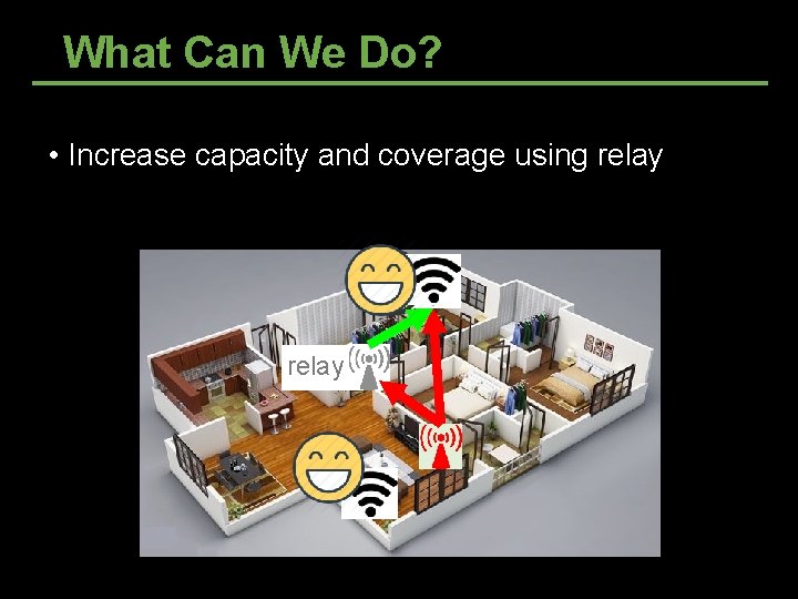
What Can We Do? • Increase capacity and coverage using relay
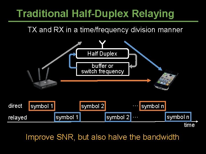
Traditional Half-Duplex Relaying TX and RX in a time/frequency division manner TX Half Duplex relayed RX buffer or switch frequency direct symbol 2 symbol 1 relayed symbol 1 … symbol n symbol 2 … symbol n time Improve SNR, but also halve the bandwidth
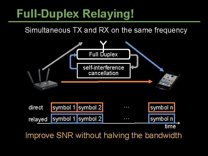
Full-Duplex Relaying! Simultaneous TX and RX on the same frequency TX relayed Full Duplex RX self-interference cancellation direct symbol 1 symbol 2 … symbol n relayed symbol 1 symbol 2 … symbol n time direct Improve SNR without halving the bandwidth
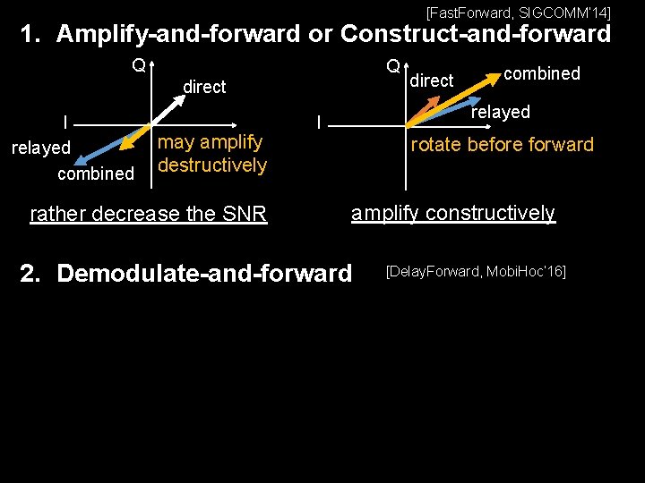
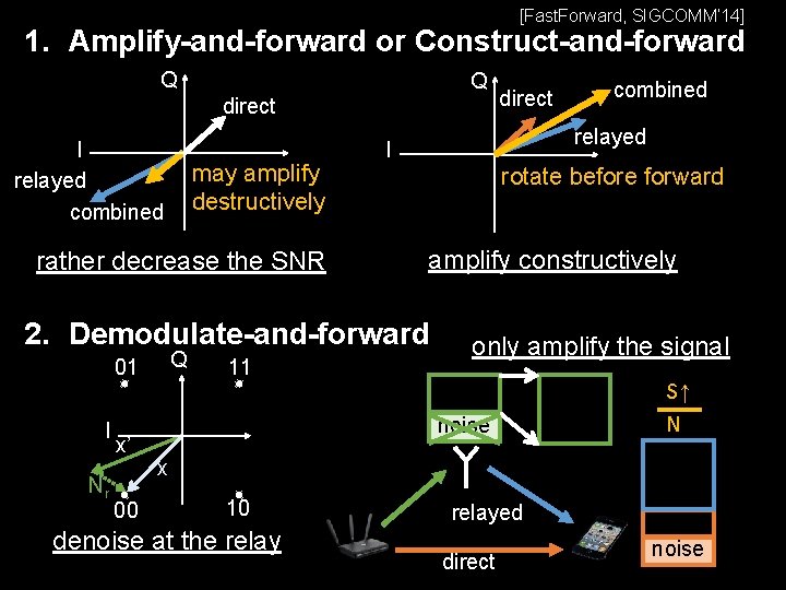
[Fast. Forward, SIGCOMM’ 14] 1. Amplify-and-forward or Construct-and-forward Q Q direct I relayed combined may amplify destructively rather decrease the SNR direct combined relayed I rotate before forward amplify constructively 2. Demodulate-and-forward [Delay. Forward, Mobi. Hoc’ 16]
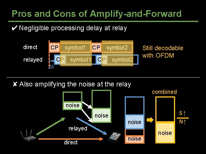
Pros and Cons of Amplify-and-Forward ✔ Negligible processing delay at relay direct CP symbol 1 CP relayed symbol 1 CP symbol 2 Still decodable with OFDM Δt ✘ Also amplifying the noise at the relay combined noise S↑ N↑ noise relayed direct noise
[Fast. Forward, SIGCOMM’ 14] 1. Amplify-and-forward or Construct-and-forward Q Q direct I relayed combined may amplify destructively rather decrease the SNR 01 I Nr x’ 00 11 combined relayed I rotate before forward amplify constructively 2. Demodulate-and-forward Q direct only amplify the signal noise S↑ N x 10 denoise at the relayed direct noise
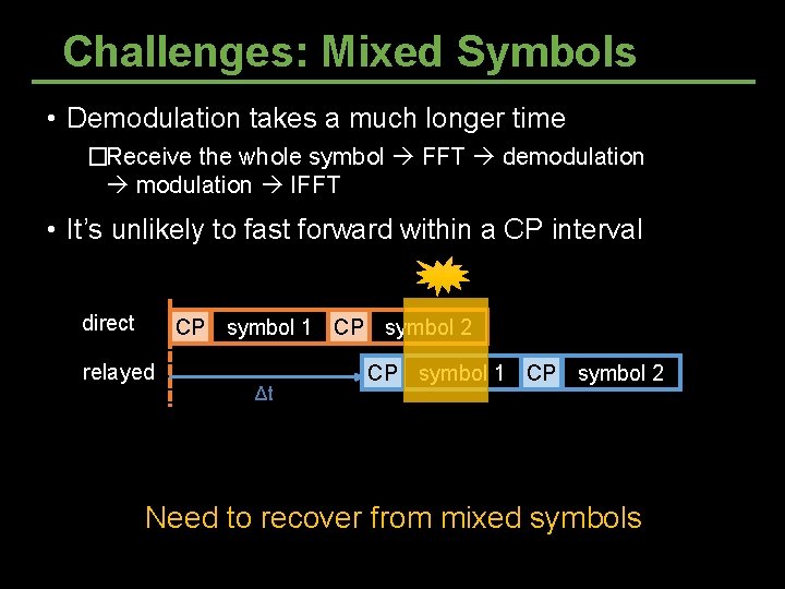
Challenges: Mixed Symbols • Demodulation takes a much longer time �Receive the whole symbol FFT demodulation IFFT • It’s unlikely to fast forward within a CP interval direct CP symbol 1 CP symbol 2 relayed Δt CP symbol 1 CP symbol 2 Inter-symbol interference at the destination Need to recover from mixed symbols
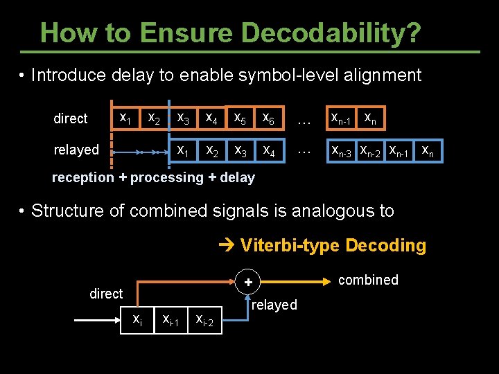
How to Ensure Decodability? • Introduce delay to enable symbol-level alignment x 1 direct x 2 relayed x 3 x 4 x 5 x 6 … xn-1 xn x 1 x 2 x 3 x 4 … xn-3 xn-2 xn-1 xn reception + processing + delay • Structure of combined signals is analogous to convolutional code Viterbi-type Decoding + direct xi xi-1 xi-2 relayed combined
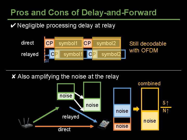
Pros and Cons of Delay-and-Forward ✔ Negligible processing delay at relay direct CP symbol 1 CP relayed symbol 1 CP symbol 2 Still decodable with OFDM Δt ✘ Also amplifying the noise at the relay combined noise S↑ N↑ noise relayed direct noise