LMDS Wireless Broadband Communications Outline Class Schedule LMDS

LMDS Wireless Broadband Communications

Outline • Class Schedule • LMDS Specification • Hughes Example

Class Schedule • • • 5. 11 LMDS 5. 18 Third Generation 5. 25 (Preparation for your Midterm) 6. 01 (Midterm) 6. 08 IP Multi-Layer Switching 6. 15 IP Multi-Layer Switching – 4 Page Final Report for Broadband Service

Dark Horse of the broadband Wireless Cable Modem ADSL

LMDS could provide upstream • LMDS could provide upstream bandwidth • usually relies on telephone line return • LMDS could provide Qo. S – Provide Point to Point Connection – Provide Point to Multi-Point Connections

Wireless World is Coming?

Wireless Broadband Communications • Fixed Access Networks – Deployment Costs and Time • Mobile Cellular Access – Mobile Users (Vehicular) • Local Area Networks – Deployments – Tetherless

DVB and DAVIC • Digital TV Applications – Standard for digital Broadcasting over • 1994 release (DVB, Digital Video Broadcasting) – Satellite – Cable Networks • Radio – below 10 GHz microwave -(MMDS) – above 20 GHz LMDS millimeter-wave Radio • Digital Audio. Visual Council – interactive Service as well

Providing More Services • DVB/DAVIC Packet Format – e. g. 7 ATM cells onto 2 MPEG 2 • Supply Broadband Service – Data – Telephony • Quick Deployment

LMDS system functional blocks Video Server Local Switch Broadband Switch Head End Television Air Interface Unit Hub Station Subscriber Set-top Unit unit Personal Computer Telephone

LMDS Applications • Local Multi-point Distribution Systems – TV Broadcasting – Telephone – Data Network
 • Based on Cellular architecture")
LMDS Characteristics • above 20 GHz (20 -40 GHz) • Based on Cellular architecture • fixed links between a multidirectional hub and a number of of fixed subcribers • line-of-sight – unobstructed path • 2 -6 km diameter
 • • Propagation Measurements and Modeling Path Loss Characteristics Delay")
Channel Modeling (Physical Layer) • • Propagation Measurements and Modeling Path Loss Characteristics Delay Characteristics Channel Coding

Point to Multiple Point System

Combined Multiple Network System with LMDS System
 • Time Slots (For each ATM Cell) Polling, Data Transmission")
MAC Protocol (ATM Solution) • Time Slots (For each ATM Cell) Polling, Data Transmission Polling Response, Collision Slot, Reserved Slots

Polling Signal • Establishments, Maintain, Terminate Connection, (e. g. Power Control, carrier frequency control ) • Synchronization (terminal enter the network)

Tunneling Protocols 802. 16 Broadband Wireless T 1 PBX PPP/V. 35 Router PPP/V. 35

Wireless Connections Protocol Spec Higher Layers Ethernet MAC Ethernet PHY Encapsulation Ethernet 802. 16 MAC Ethernet 802. 16 PHY Wireless Link

BS/CPE Communications • BS- Base Station – Access Control – Authentication • CPE (Customer Premise Equipment) – must achieve down
 Bandwidth Request Contention Slots (QPSK) CPE Schedule")
Uplink Subframe structure Registration Contention Slots (QPSK) Bandwidth Request Contention Slots (QPSK) CPE Schedule Data (QAM)

Mobile cellular and WLL application

Typical Architecture of Remote Terminal

Typical Architecture of Hub Terminal

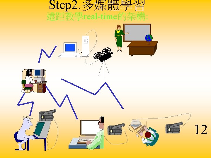
Wireless ATM 12

Frequency Reuse • 4 Sectors – rectangular cells with 90 sector antenna • 3 Sectors – Hexagonal cell pattern with 120 sectors
 ex: crosspolarization þPower control þ天線方向性 A B B A")
Base station placement þ頻率的管理(assignment, reuse) ex: crosspolarization þPower control þ天線方向性 A B B A Major Sources of Interference for downlink 9 Major Sources of Interference for uplink

Higher-Level Modulations • QAM • QPSK

AIReach™ Broadband Dual-Modulation Capability • • • Ultra-high capacity with 64 -QAM (60 Mbps gross) – 4. 8 b/Hz spectral efficiency Greater range with QPSK (20 Mbps gross) – 1. 6 b/Hz spectral efficiency AIReach. TM Broadband supports both modes (slot by slot) simultaneously, optimizing system capacity and range

AIReach™ Broadband Dual. Mode Transport Capability REMOTE TERMINAL CIRCUIT SOURCE TDM MULTIPLEXING PACKET SOURCE ATM CONVERSION HUB TERMINAL TDM I/F AIR INTERFACE G-17840 P 10/05/99 AIR INTERFACE ATM I/F TDM STM-1 ATM STM-1 OTHER REMOTE TERMINALS • AIReach. TM supports existing infrastructure through TDM and future migration through ATM (future proof system!) • TDM source is multiplexed to hub interface – TDM can be processed as TDM or ATM on air interface – ATM source can be multiplexed to air interface directly
 –")
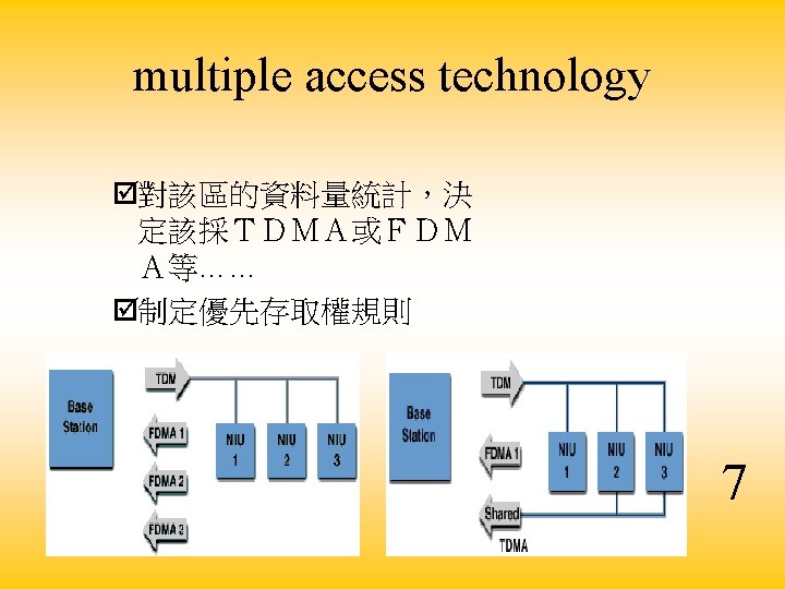
Multiple Access Techniques • TDMA • FDMA • CDMA – Walsh-Hadamard Sequence (Orthogonal) – Nonorthogonal CDMA (PN-CDMA)

PMP System Elements

Goal of the project • IP Multimedia Application through LMDS – ex: Voice over Ip , Video conference • The first demo site in Taiwan: study the utilization of LMDS in Taiwan • Extend the broadband network into wireless (Internet II)

Experiments and Research • Two way video conference experiments • IP network experiments • Network Interconnection – Wireless LAN – Eithernet Experiments – Direct PC • ATM interface experiments (will be planned for the next LMDS with ATM interface delivery)

Network Interconnection 衛星本體 downlink LMDS uplink Wireless Lan Internet

LMDS Deployment Graph RT 2 Hub RT 1 Computer Center Telemetry Center

Architechture of the Demo

LMDS Leaning Community Cooperation among NCU School, Telecommunication Lab and Neighboring Community National Central University 2020/11/30

Step. 1 LMDS Architecture 11 2020/11/30

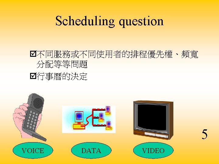
Research Issues LMDS for Distant Learning • • Scheduling question multiple access technology Transmission impact Base station placement 4 2020/11/30
 –")
Transmission impact – Atmospheric attenuation – Dynamic data rate – TCP/IP的調整(ex: window size) – higher power, reduce cell size Application TCP IP Data Link Physical 7 6 8 5 1 2 3 4 8 1 7 2 6 3 5 4 8

Future Works • Intelligent Routing – Select the best one way to transmit data LMDS ATM Wireless

How to do multicast over ATM in LMDS? LMDS link mobile terminal ATM Backbone base station WATM switch

Guaranty of Qo. S in LMDS Ex: Different rate based on different data type 30% 20% 50%
- Slides: 47