Wakefield Calculations for the Synchrotron Light Source Petra
- Slides: 19
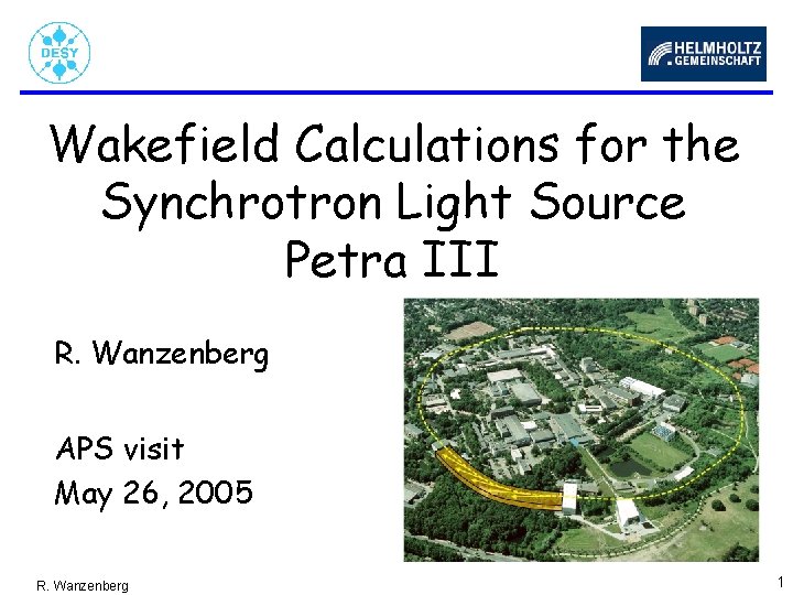
Wakefield Calculations for the Synchrotron Light Source Petra III R. Wanzenberg APS visit May 26, 2005 R. Wanzenberg 1
Outline • • • Synchrotron Light Sources at DESY The Synchroton Light Source PETRA III Wakefields Numerical calculations Single Bunch Instabilities Conclusion R. Wanzenberg 2
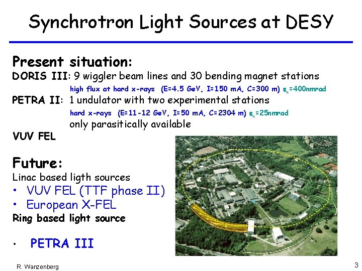
Synchrotron Light Sources at DESY Present situation: DORIS III: 9 wiggler beam lines and 30 bending magnet stations high flux at hard x-rays (E=4. 5 Ge. V, I=150 m. A, C=300 m) ex=400 nmrad PETRA II: 1 undulator with two experimental stations hard x-rays (E=11 -12 Ge. V, I=50 m. A, C=2304 m) ex=25 nmrad VUV FEL only parasitically available Future: Linac based ligth sources • VUV FEL (TTF phase II) • European X-FEL Ring based light source • PETRA III R. Wanzenberg 3
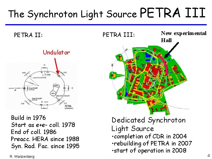
The Synchroton Light Source PETRA II: PETRA III New experimental Hall Undulator Build in 1976 Start as e+e- coll. 1978 End of coll. 1986 Preacc. HERA since 1988 Syn. Rad. Fac. since 1995 R. Wanzenberg Dedicated Synchroton Light Source • completion of CDR in 2004 • rebuilding of PETRA in 2007 • start of operation in 2008 4
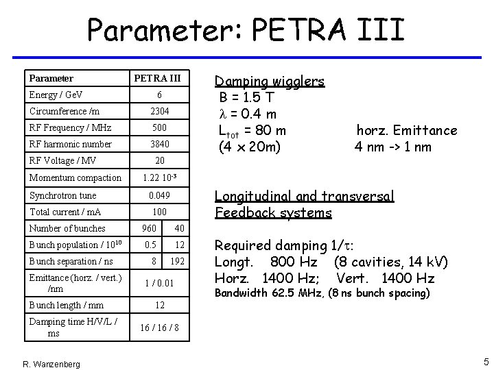
Parameter: PETRA III Parameter PETRA III Energy / Ge. V 6 Circumference /m 2304 RF Frequency / MHz 500 RF harmonic number 3840 RF Voltage / MV Momentum compaction 1. 22 10 -3 0. 049 Total current / m. A 100 Longitudinal and transversal Feedback systems Number of bunches 960 40 Bunch population / 1010 0. 5 12 8 192 Emittance (horz. / vert. ) /nm Bunch length / mm Damping time H/V/L / ms R. Wanzenberg horz. Emittance 4 nm -> 1 nm 20 Synchrotron tune Bunch separation / ns Damping wigglers B = 1. 5 T l = 0. 4 m Ltot = 80 m (4 x 20 m) 1 / 0. 01 Required damping 1/t: Longt. 800 Hz (8 cavities, 14 k. V) Horz. 1400 Hz; Vert. 1400 Hz Bandwidth 62. 5 MHz, (8 ns bunch spacing) 12 16 / 8 5
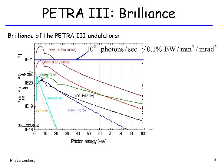
PETRA III: Brilliance of the PETRA III undulators: R. Wanzenberg 6
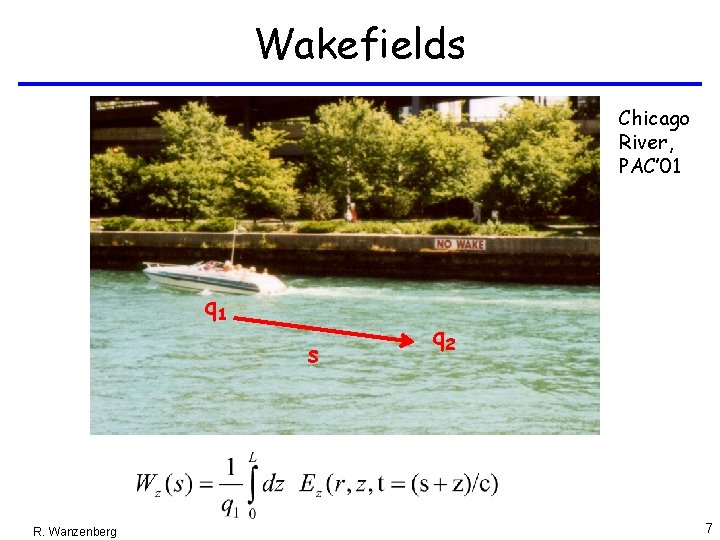
Wakefields Chicago River, PAC’ 01 q 1 s R. Wanzenberg q 2 7
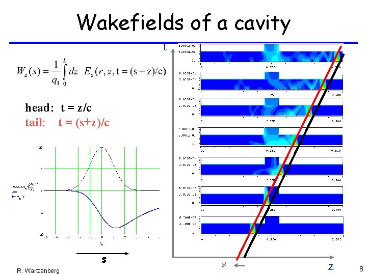
Wakefields of a cavity t head: t = z/c tail: t = (s+z)/c s R. Wanzenberg s z 8
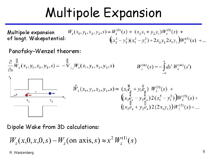
Multipole Expansion Multipole expansion of longt. Wakepotential: Panofsky-Wenzel theorem: Dipole Wake from 3 D calculations: R. Wanzenberg 9
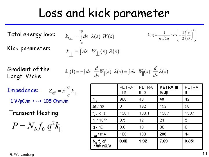
Loss and kick parameter Total energy loss: Kick parameter: Gradient of the Longt. Wake Impedance: 1 V/p. C/m < --> 105 Ohm/m Transient Heating: R. Wanzenberg PETRA III a PETRA III b/up PETRA II Nb 960 40 40 42 Dt / ns 8 192 96 f 0 / k. Hz 130. 1 N / 1010 0. 5 12 24 5 q / n. C 0. 8 19 38 8 Itot / m. A 100 200 44 Nb f 0 q 2 / W/ n. C/V 0. 08 1. 92 7. 69 0. 351 10
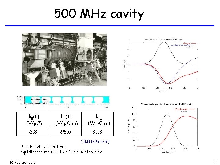
500 MHz cavity k||(0) (V/p. C) k||(1) (V/ p. C m) k^ (V/ p. C m) -3. 8 -96. 0 35. 8 ( 3. 8 k. Ohm/m) Rms bunch length 1 cm, equidistant mesh with a 0. 5 mm step size R. Wanzenberg 11
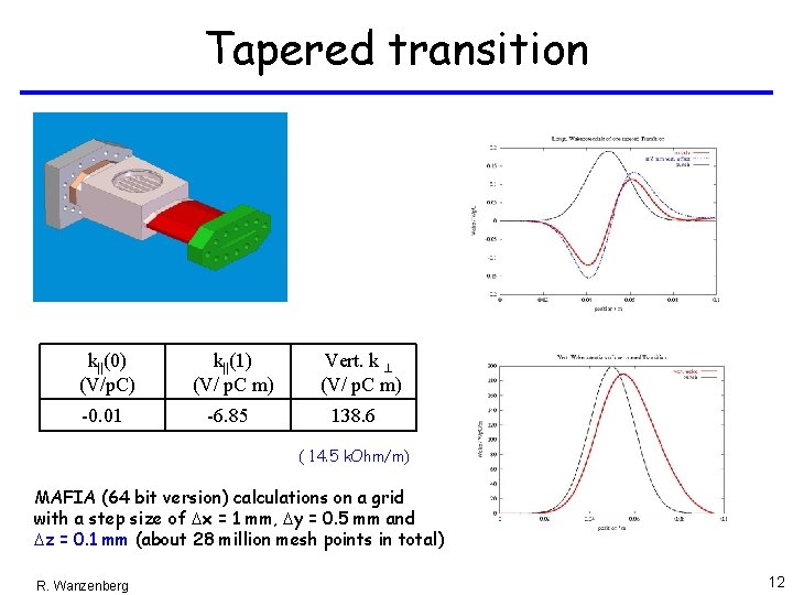
Tapered transition k||(0) (V/p. C) k||(1) (V/ p. C m) -0. 01 -6. 85 Vert. k ^ (V/ p. C m) 138. 6 ( 14. 5 k. Ohm/m) MAFIA (64 bit version) calculations on a grid with a step size of Dx = 1 mm, Dy = 0. 5 mm and Dz = 0. 1 mm (about 28 million mesh points in total) R. Wanzenberg 12
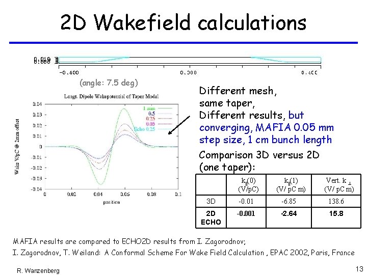
2 D Wakefield calculations (angle: 7. 5 deg) Different mesh, same taper, Different results, but converging, MAFIA 0. 05 mm step size, 1 cm bunch length Comparison 3 D versus 2 D (one taper): k||(0) (V/p. C) k||(1) (V/ p. C m) Vert. k ^ (V/ p. C m) 3 D -0. 01 -6. 85 138. 6 2 D ECHO -0. 001 -2. 64 15. 8 MAFIA results are compared to ECHO 2 D results from I. Zagorodnov; I. Zagorodnov, T. Weiland: A Conformal Scheme For Wake Field Calculation , EPAC 2002, Paris, France R. Wanzenberg 13
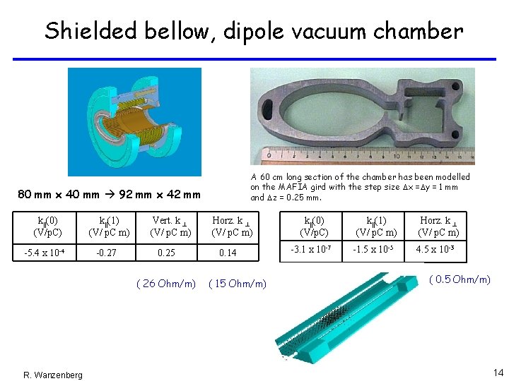
Shielded bellow, dipole vacuum chamber A 60 cm long section of the chamber has been modelled on the MAFIA gird with the step size Dx =Dy = 1 mm and Dz = 0. 25 mm. 80 mm x 40 mm 92 mm x 42 mm k||(0) (V/p. C) -5. 4 x 10 -4 k||(1) (V/ p. C m) -0. 27 Vert. k ^ (V/ p. C m) 0. 25 ( 26 Ohm/m) R. Wanzenberg Horz. k ^ (V/ p. C m) 0. 14 ( 15 Ohm/m) k||(0) (V/p. C) -3. 1 x 10 -7 k||(1) (V/ p. C m) -1. 5 x 10 -5 Horz. k ^ (V/ p. C m) 4. 5 x 10 -3 ( 0. 5 Ohm/m) 14
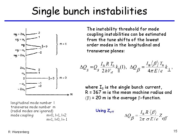
Single bunch instabilities The instability threshold for mode coupling instabilities can be estimated from the tune shifts of the lowest order modes in the longitudinal and transverse planes: longitudinal mode number l transverse mode number m (radial modes are ignored) mode coupling: m=0, l=1, l=2 m=1, l=0, l=-1 R. Wanzenberg where IB is the single bunch current, R = 367 m is the mean machine radius and ábñ = 20 m is the average b-function. Using Zeff 15
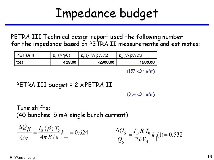
Impedance budget PETRA III Technical design report used the following number for the impedance based on PETRA II measurements and estimates: PETRA II total k|| (V/p. C) -128. 00 k||(1) (V/ p. C/ m) k^ (V/ p. C/ m) -2900. 00 1500. 00 (157 k. Ohm/m) PETRA III budget = 2 x PETRA II (314 k. Ohm/m) Tune shifts: (40 bunches, 5 m. A single bunch current) R. Wanzenberg 16
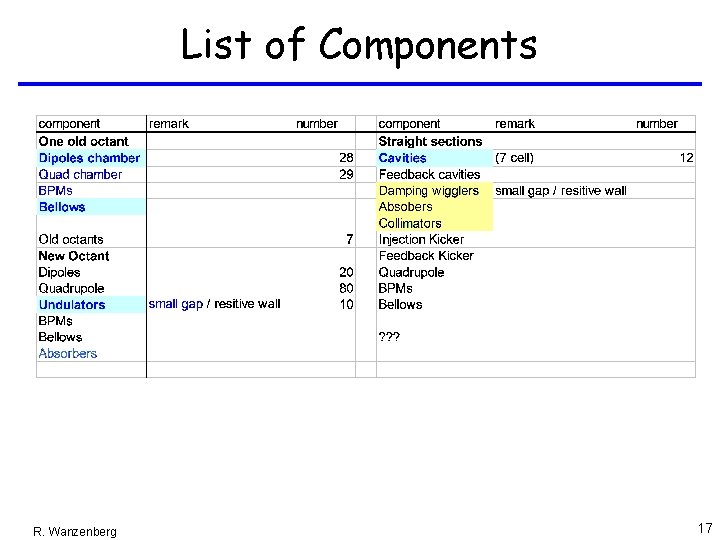
List of Components R. Wanzenberg 17
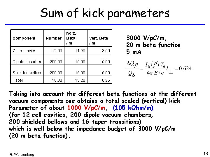
Sum of kick parameters horz. Beta /m Component Number 7 -cell cavity 12. 00 11. 50 13. 50 Dipole chamber 200. 00 15. 00 Shielded bellow 200. 00 15. 00 16. 00 15. 20 6. 25 Taper vert. Beta /m 3000 V/p. C/m, 20 m beta function 5 m. A Taking into account the different beta functions at the different vacuum components one obtains a total scaled (vertical) kick Parameter of about 1000 V/p. C/m, (105 k. Ohm/m) (for 12 cell cavities, 200 dipole vacuum chambers, 200 shielded bellows and 16 taper transitions) which is well below the impedance budget of 3000 V/p. C/m (20 m beta function). R. Wanzenberg 18
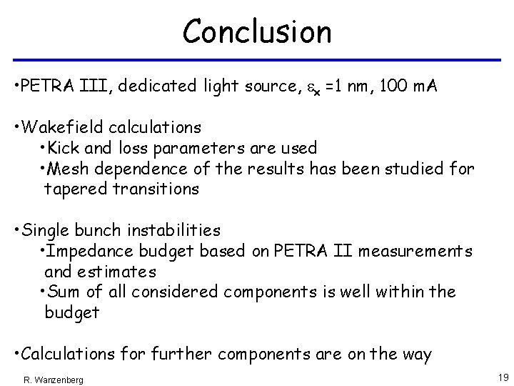
Conclusion • PETRA III, dedicated light source, ex =1 nm, 100 m. A • Wakefield calculations • Kick and loss parameters are used • Mesh dependence of the results has been studied for tapered transitions • Single bunch instabilities • Impedance budget based on PETRA II measurements and estimates • Sum of all considered components is well within the budget • Calculations for further components are on the way R. Wanzenberg 19