
LHC Beam Size Measurement Review Possible synchrotron light

LHC Beam Size Measurement Review Possible synchrotron light upgrades for HL-LHC E. Bravin, G. Trad, G. Sousa, D. Butti logo area LHC Beam Size Measurement review – 1 -2 October 2019 – CERN
Foreword § There is no official upgrade plan for the BSRT § Modifications and improvements are for the moment financed by the exploitation budget § Run 3 will provide important lessons § For the HL-LHC project a new synchrotron light extraction per beam will be designed and installed § The purpose of this new extraction is to accommodate the HALO monitor (aka coronagraph) and the streak cameras for monitoring the crabbing § The halo monitor is presently under development § The need of streak cameras is still under discussion logo area Enrico Bravin (BE-BI) 2
Content § Present status and limitations § Possible improvements for the imaging system § Mechanics § Optics § Acquisition § Alternative measurements § Double slit interferometer § Pin-Hole camera § Beam halo monitor § New light extractions logo area Enrico Bravin (BE-BI) 3
BSRT Status and Limitations § Beam size derived from imaging of Synchrotron Radiation emitted in LSS 4 § Complex source: Undulator, D 3 -edge, D 3 -core, D 3 edge on the other side, reflections, diffusion … § This together with diffraction limits the optical resolution § SR from D 3 extend in the UV, Undulator even in XRays § Damage to the optical components § Acquisition relies on Image-Intensifiers for Bby. B gating § Rapid wear of the photocathode, need to keep light low (reduce S/N) and slow the acquisition (long scans) logo area Enrico Bravin (BE-BI) 4
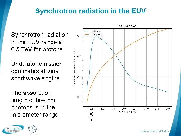
Synchrotron radiation in the EUV range at 6. 5 Te. V for protons Undulator emission dominates at very short wavelengths logo area 500 e. V The absorption length of few nm photons is in the micrometer range Enrico Bravin (BE-BI) 5
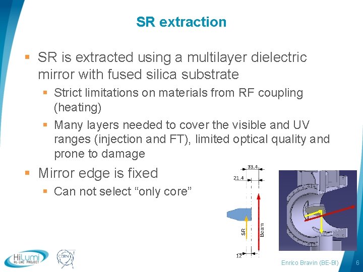
SR extraction § SR is extracted using a multilayer dielectric mirror with fused silica substrate § Strict limitations on materials from RF coupling (heating) § Many layers needed to cover the visible and UV ranges (injection and FT), limited optical quality and prone to damage § Mirror edge is fixed § Can not select “only core” logo area Enrico Bravin (BE-BI) 6
SR extraction improvements § Ramp down undulators at high energy § Separate extraction of UV and visible § § Two mirrors (impedance? ) OR get rid of UV, gain of UV need to be studied Better quality mirrors (flatness) Less sensitive to heat deposition § Implement a dynamic position for the mirror § Place the mirror closer to the beam as the energy increases (size shrinks) § Requires actuators similar to collimators § Allow to select only the core of D 3 as source § Add an X-Ray filter upstream of the mirror (Fused silica slab) § Reduce the damage to the components downstream logo area Enrico Bravin (BE-BI) 7
Optics § Observed UV induced damage on: Viewport, UVfilters, Wedge splitter § Cause of damage not fully understood, for the viewport and wedge, may be due to Fluorine presence in the enclosure (etching) § Replace all mirrors on the optical table (Mg. F coated) § Mask the synchrotron light to avoid UV on cables/mounts etc. § UV-filters probably suffer from burns § Move filters to location where SR is defocused § LSF larger than expected, not understood § More refined simulations § Investigate different optics solutions (focal lengths, Cassegrain, etc. ) logo area Enrico Bravin (BE-BI) 8
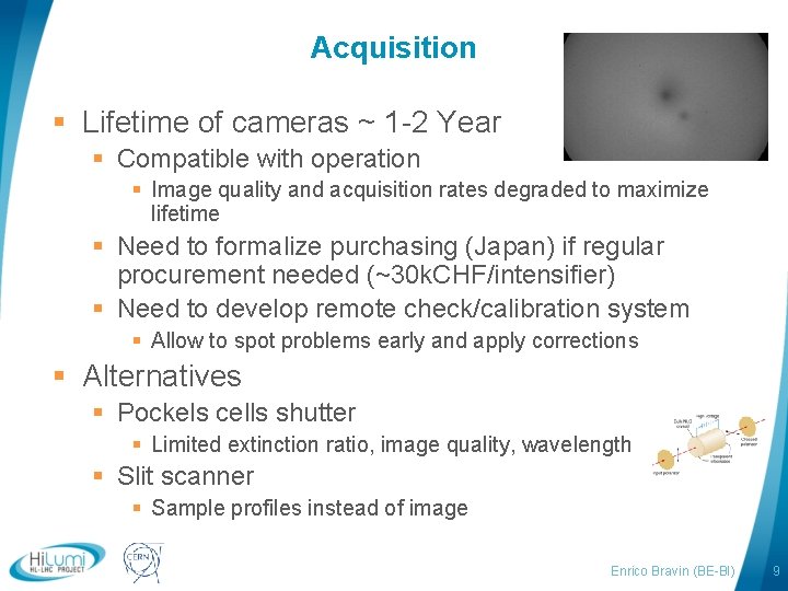
Acquisition § Lifetime of cameras ~ 1 -2 Year § Compatible with operation § Image quality and acquisition rates degraded to maximize lifetime § Need to formalize purchasing (Japan) if regular procurement needed (~30 k. CHF/intensifier) § Need to develop remote check/calibration system § Allow to spot problems early and apply corrections § Alternatives § Pockels cells shutter § Limited extinction ratio, image quality, wavelength § Slit scanner § Sample profiles instead of image logo area Enrico Bravin (BE-BI) 9
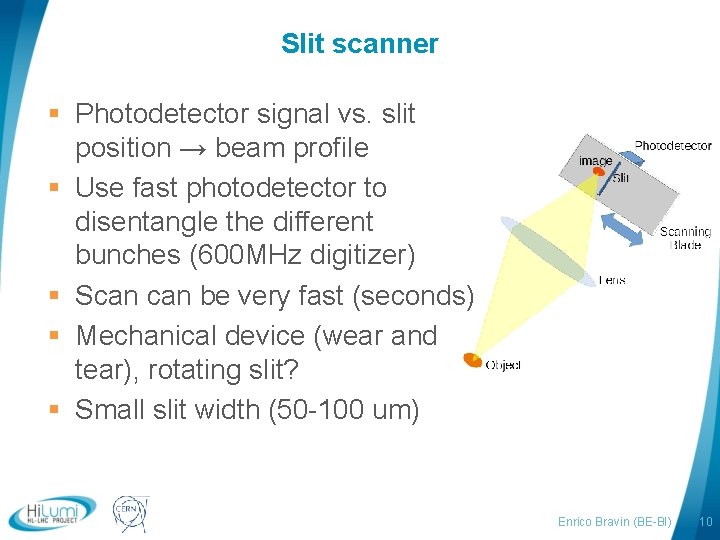
Slit scanner § Photodetector signal vs. slit position → beam profile § Use fast photodetector to disentangle the different bunches (600 MHz digitizer) § Scan be very fast (seconds) § Mechanical device (wear and tear), rotating slit? § Small slit width (50 -100 um) logo area Enrico Bravin (BE-BI) 10
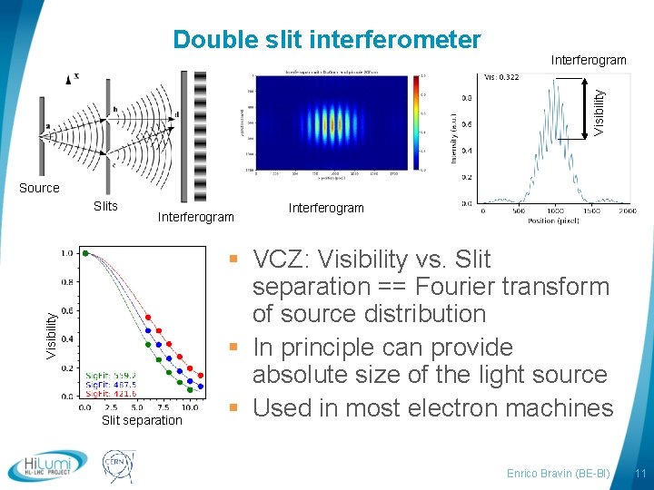
Interferogram Visibility Double slit interferometer Source Interferogram Visibility Slits Slit separation logo area Interferogram § VCZ: Visibility vs. Slit separation == Fourier transform of source distribution § In principle can provide absolute size of the light source § Used in most electron machines Enrico Bravin (BE-BI) 11
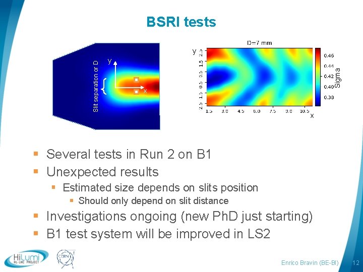
BSRI tests y Sigma Slit separation or D y x x § Several tests in Run 2 on B 1 § Unexpected results § Estimated size depends on slits position § Should only depend on slit distance § Investigations ongoing (new Ph. D just starting) § B 1 test system will be improved in LS 2 logo area Enrico Bravin (BE-BI) 12
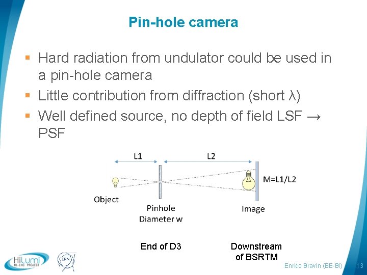
Pin-hole camera § Hard radiation from undulator could be used in a pin-hole camera § Little contribution from diffraction (short λ) § Well defined source, no depth of field LSF → PSF End of D 3 logo area Downstream of BSRTM Enrico Bravin (BE-BI) 13
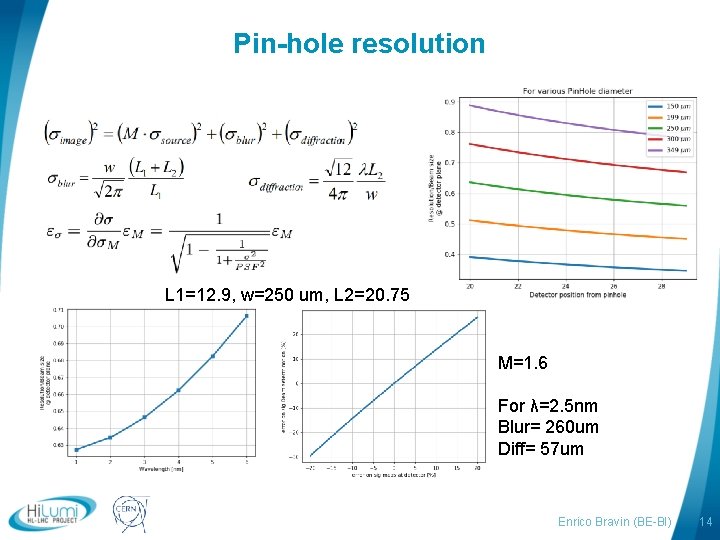
Pin-hole resolution L 1=12. 9, w=250 um, L 2=20. 75 M=1. 6 For λ=2. 5 nm Blur= 260 um Diff= 57 um logo area Enrico Bravin (BE-BI) 14
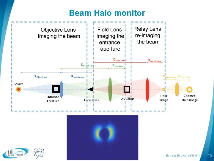
Beam Halo monitor logo area Enrico Bravin (BE-BI) 15
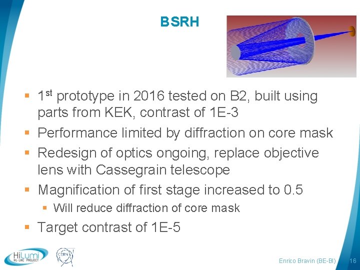
BSRH § 1 st prototype in 2016 tested on B 2, built using parts from KEK, contrast of 1 E-3 § Performance limited by diffraction on core mask § Redesign of optics ongoing, replace objective lens with Cassegrain telescope § Magnification of first stage increased to 0. 5 § Will reduce diffraction of core mask § Target contrast of 1 E-5 logo area Enrico Bravin (BE-BI) 16
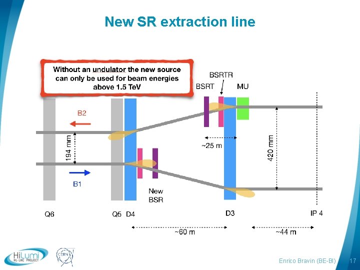
New SR extraction line logo area Enrico Bravin (BE-BI) 17
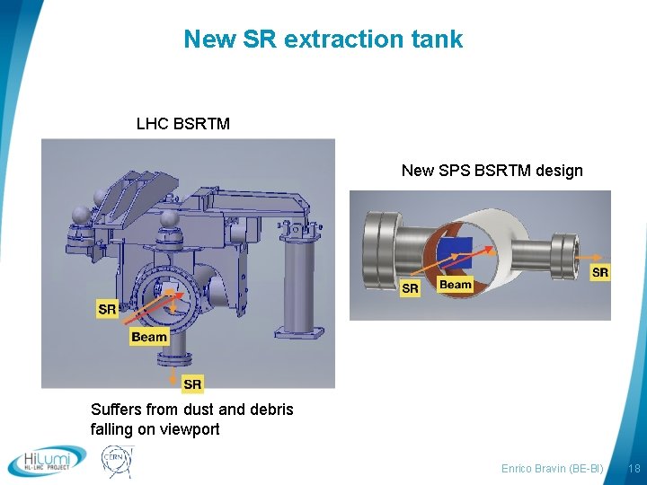
New SR extraction tank LHC BSRTM New SPS BSRTM design Suffers from dust and debris falling on viewport logo area Enrico Bravin (BE-BI) 18
Conclusions § No major upgrade plan for the BSRT § HL-LHC will profit from the continuous improvements of the system during LS 2 and Run 3 § Interferometer proceeding well, will be made operational during Run 3 § Pin-hole camera could be interesting, but many technical difficulties to implement (impedance) § New SR extraction lines offer flexibility to reshuffle/optimize the different instruments logo area Enrico Bravin (BE-BI) 19
- Slides: 19