
SESAME Synchrotron Light for Experimental Science and Applications

- Slides: 49
SESAME Synchrotron Light for Experimental Science and Applications in the Middle East JSPS Asien Science Seminar Synchrotron Radiation Science Dieter Einfeld Amman, October 2002
Introduction Based on the workshops held in the Middle East Region and other activities of the SESAME Scientific Committee, the scientific program for SESAME includes: Ø Structural molecular biology Ø Molecular environnemental science Ø Surface and interface science Ø Micro mechanical devices Ø X-ray imaging Ø Archaeological microanalysis Ø Material characterization Ø Medical applications Most of these applications require hard x-rays up to 20 ke. V photons.
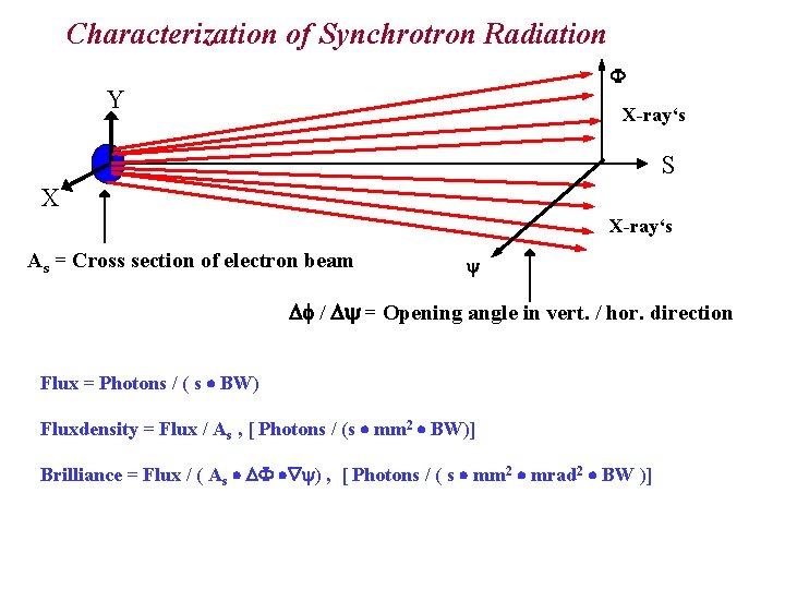
Characterization of Synchrotron Radiation Y X-ray‘s S X X-ray‘s As = Cross section of electron beam / = Opening angle in vert. / hor. direction Flux = Photons / ( s BW) Fluxdensity = Flux / As , [ Photons / (s mm 2 BW)] Brilliance = Flux / ( As ) , [ Photons / ( s mm 2 mrad 2 BW )]
Performance of a Light Source The performance of a synchrotron light source is given by: the brilliance of the emitted radiation the overall length of the straight sections the emitted photon spectrum The brilliance: The brilliance is proportional to the photon flux per area of the source size, and opening angle of the radiation. Both factors are proportional to the emittance of the stored electron beam. To increase the brilliance further more one introduces wigglers and undulators to enlarge the number of source points.
Performance of a Light Source Length of the straight sections: According to the attraction of the synchrotron radiation, a light source should provide the radiation simultaneously to a lot of users. Hence the performance of a synchrotron light source is proportional to the number of useable long straight sections. The photon spectrum: The different users are asking for a special spectrum range. The highest photon energy of the spectrum from the bending magnet, the wiggler and the undulator is proportional to the square of the energy of the stored electrons. So, the performance of the machine should also proportional to the energy. The following parameters of the machine determine the performance of a synchrotron light source: the emittance the overall length of the straight sections the energy
History of SESAME Idea to upgrade BESSY I (1997) Proposal for SESAME to UNESCO DG (1999) Establishment of Interim Council Setting up of Advisory Committees (international) Green Book (Technical Proposal) (1999) Site Decision Al-Balqa Applied Universit Training Programme initiated (Oct. 2000) Financing of BESSY I dismantling (Aug 2000) Appointment of Technical Director (Sept. 2001) New Advisory Committees (from region)(Dec. 2001) Shipping of BESSY I components (May 2002
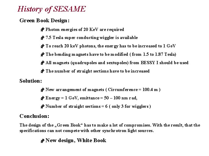
History of SESAME Green Book Design: Photon energies of 20 Ke. V are required 7. 5 Tesla super conducting wiggler is available To reach 20 ke. V photons, the energy has to be increased to 1 Ge. V The bending magnets have to be modified ( from 1. 5 to 1. 87 Tesla) All magnets (quadrupoles and sextupoles) from BESSY I should be used The number of straight sections have to be increased Solution: New arrangement of magnets ( Circumference = 100. 4 m ) Energy = 1 Ge. V, emittance = 50 – 100 nm rad, Number of straight sections = 6 ( only 3 for wigglers ) Conclusion: The design of the „Green Book“ has to make a lot of compromises. With the result, that the specifications can not compete with other synchrotron light sources. New design, White Book
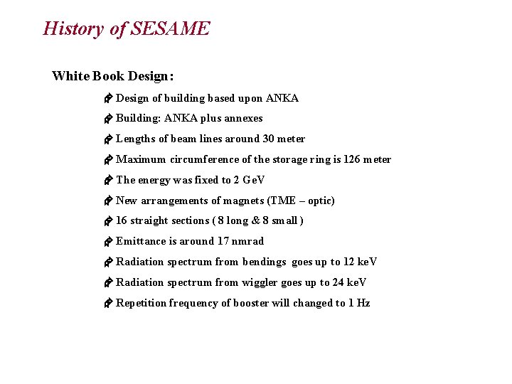
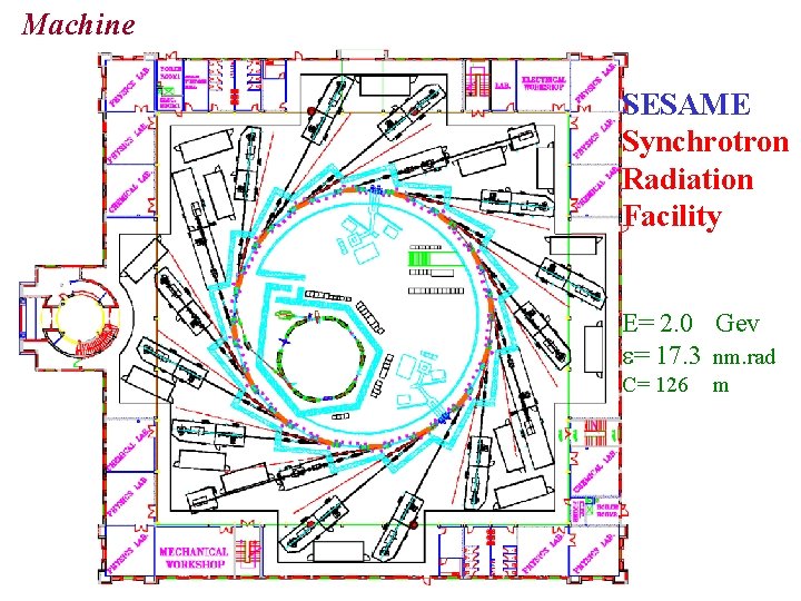
History of SESAME White Book Design: Design of building based upon ANKA Building: ANKA plus annexes Lengths of beam lines around 30 meter Maximum circumference of the storage ring is 126 meter The energy was fixed to 2 Ge. V New arrangements of magnets (TME – optic) 16 straight sections ( 8 long & 8 small ) Emittance is around 17 nmrad Radiation spectrum from bendings goes up to 12 ke. V Radiation spectrum from wiggler goes up to 24 ke. V Repetition frequency of booster will changed to 1 Hz
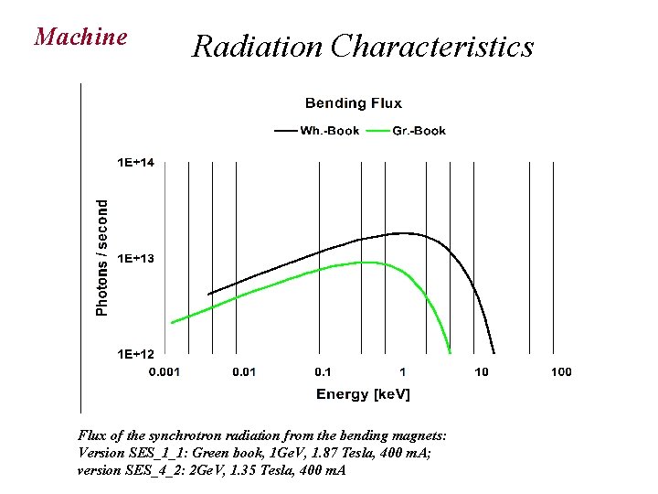
Machine Radiation Characteristics Flux of the synchrotron radiation from the bending magnets: Version SES_1_1: Green book, 1 Ge. V, 1. 87 Tesla, 400 m. A; version SES_4_2: 2 Ge. V, 1. 35 Tesla, 400 m. A
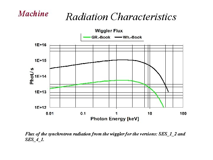
Machine Radiation Characteristics Flux of the synchrotron radiation from the wiggler for the versions: SES_1_2 and SES_4_1.
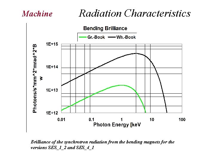
Machine Radiation Characteristics Brilliance of the synchrotron radiation from the bending magnets for the versions SES_1_2 and SES_4_1
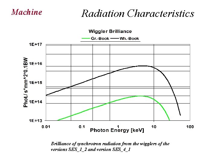
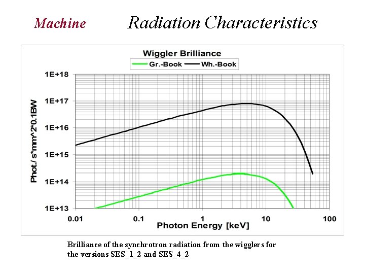
Machine Radiation Characteristics Brilliance of synchrotron radiation from the wigglers of the versions SES_1_2 and version SES_4_1
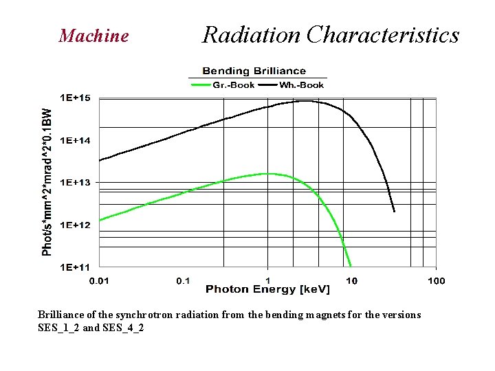
Machine Radiation Characteristics Brilliance of the synchrotron radiation from the bending magnets for the versions Brilliance of the synchrotron radiation from the bending magnets for SES_1_2 and SES_4_2 the versions SES_1_2, SES_3_2, SES_2_2 and SES_4_2.
Machine tics Radiation Characteristics Brilliance of the synchrotron radiation from the wigglers for the versions SES_1_2 and SES_4_2
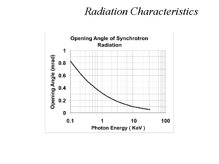
Radiation Characteristics
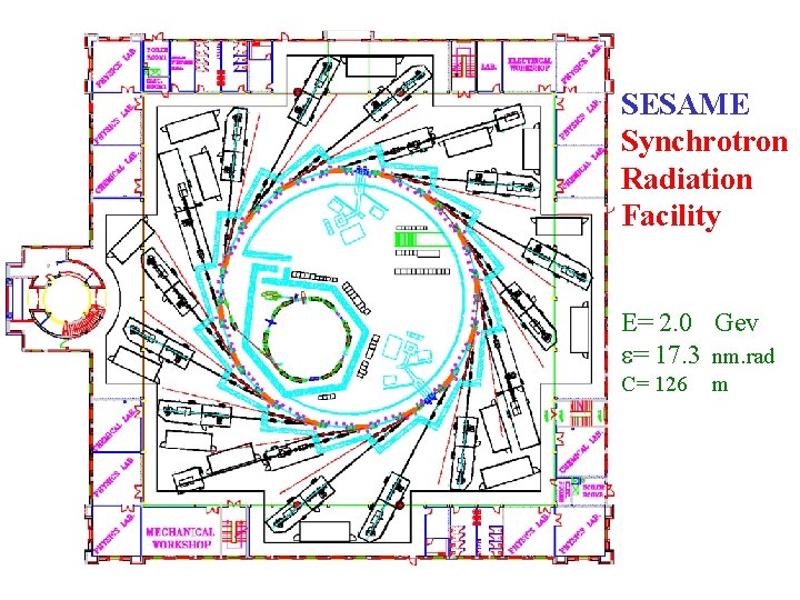
Machine SESAME Synchrotron Radiation Facility E= 2. 0 Gev = 17. 3 nm. rad C= 126 m
Machine
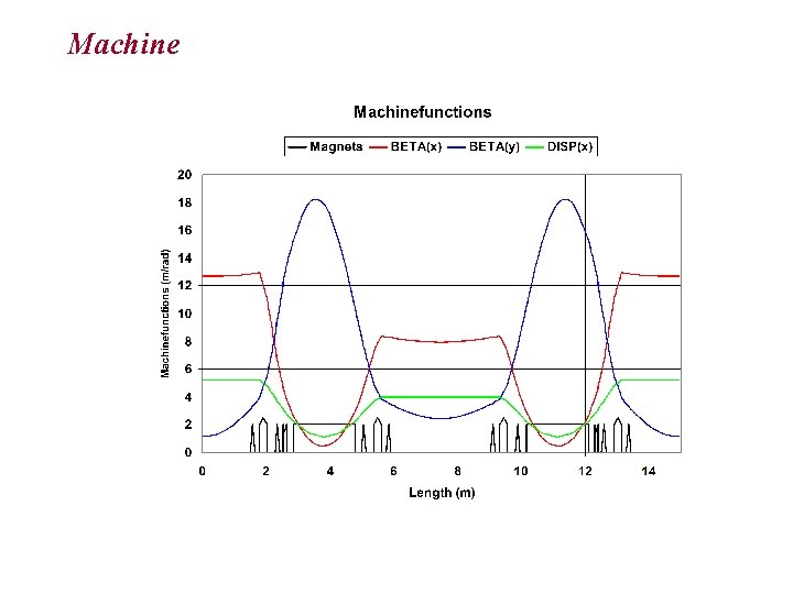
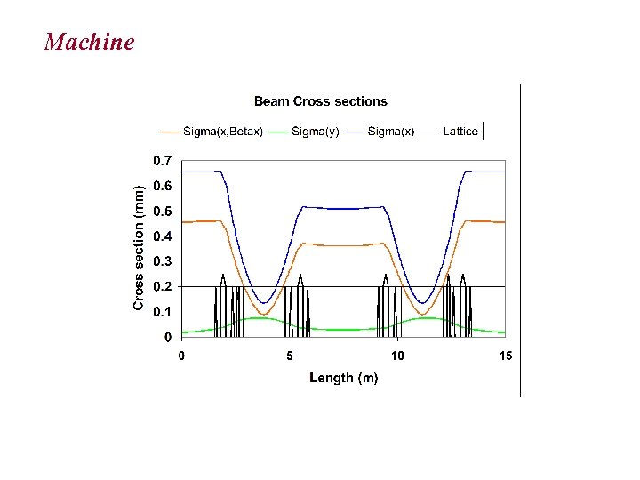
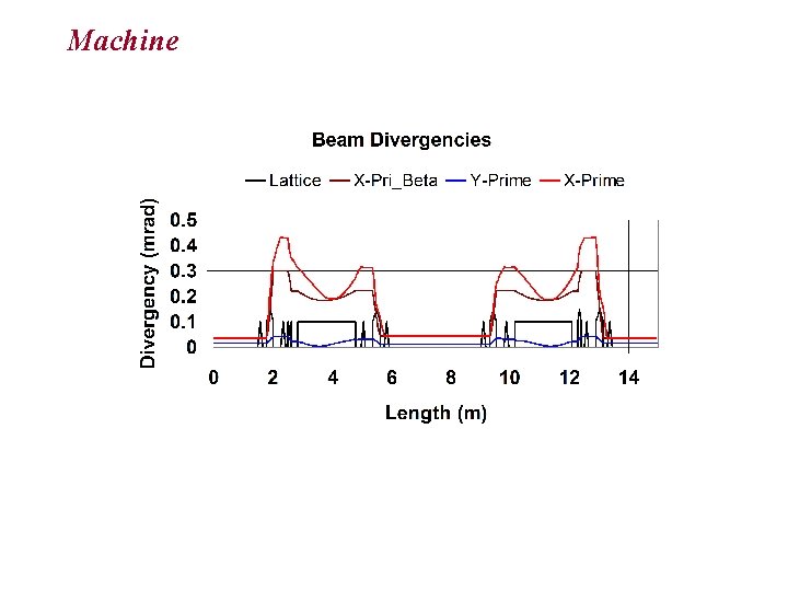
Machine am Optics Optical functions of SESAME lattice, the green line represents dispersion. Horizontal and vertical correctors are represented in red and blue.
Machine
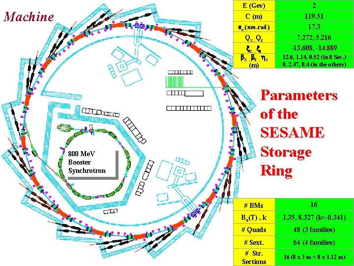
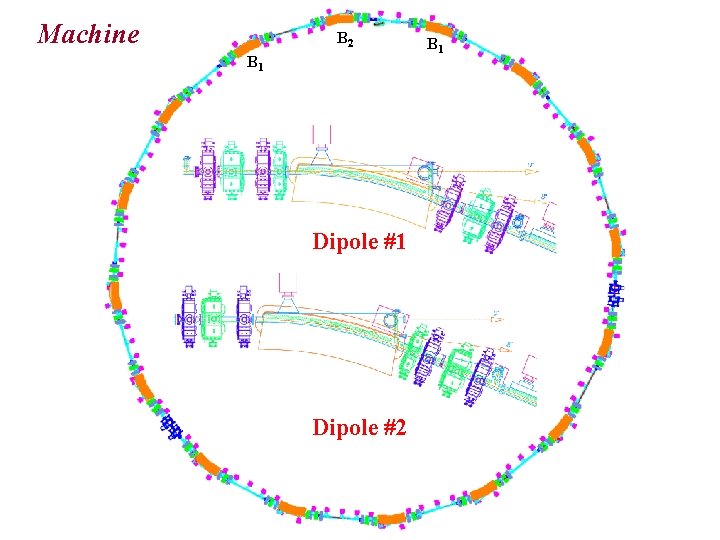
Machine 800 Me. V Booster Synchrotron E (Gev) 2 C (m) 119. 51 x (nm. rad) 17. 3 Qx , Qz 7. 272, 5. 216 x , z , x (m) -13. 608, -14. 889 12. 6, 1. 14, 0. 52 (in 8 Sec. ) 8, 2. 47, 0. 4 (in the others) Parameters of the SESAME Storage Ring # BMs 16 Bo(T) , k 1. 35, 8. 327 (k=-0. 341) # Quads 48 (3 families) # Sext. 64 (4 families) # Str. Sections 16 (8 x 3 m + 8 x 3. 12 m)
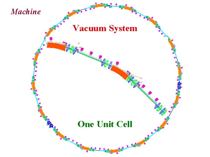
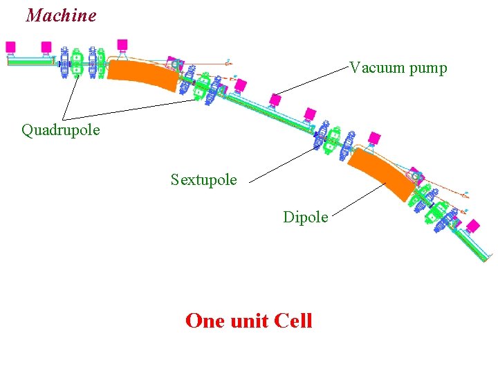
Machine Vacuum System One Unit Cell
Machine B 2 B 1 Dipole #2 B 1
Machine Vacuum pump Quadrupole Sextupole Dipole One unit Cell
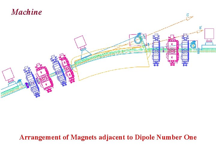
Machine Arrangement of Magnets adjacent to Dipole Number One
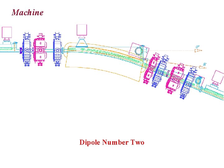
Machine Dipole Number Two
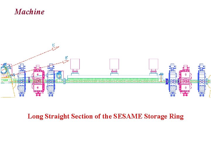
Machine Long Straight Section of the SESAME Storage Ring
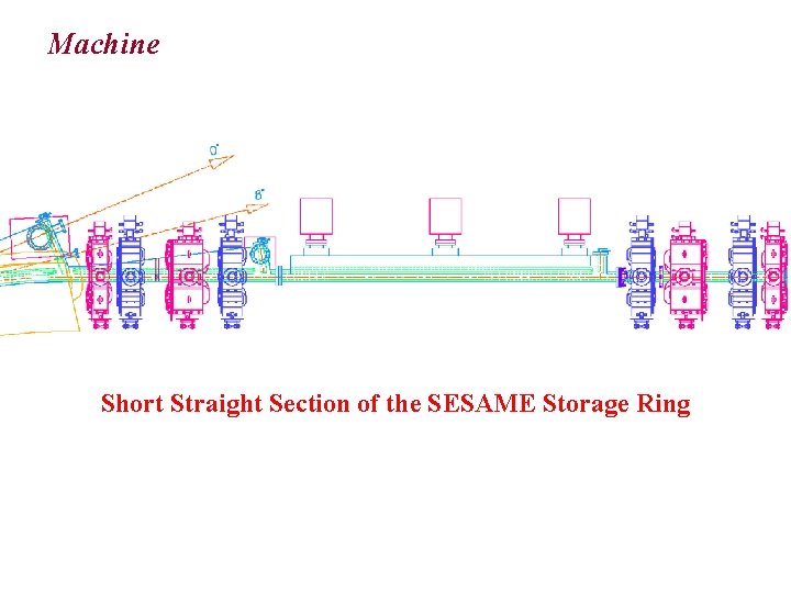
Machine Short Straight Section of the SESAME Storage Ring
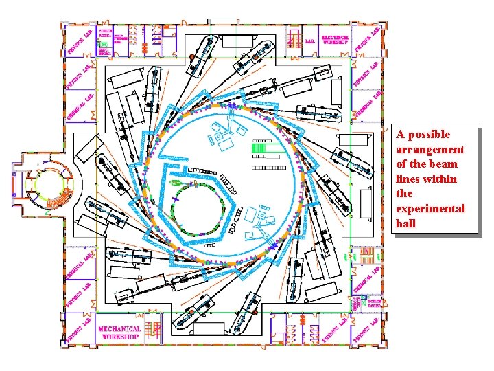
A possible arrangement of the beam lines within the experimental hall
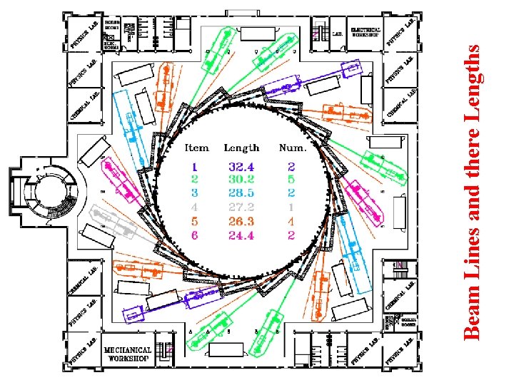
Beam Lines and there Lengths
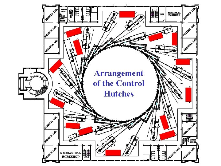
Arrangement of the Control Hutches
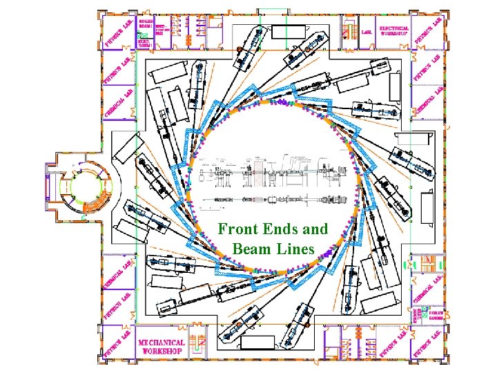
Front Ends and Beam Lines
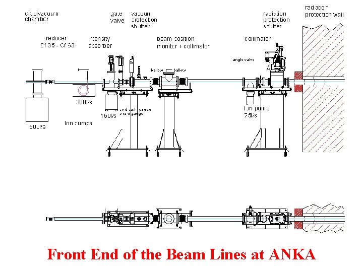
Front End of the Beam Lines at ANKA
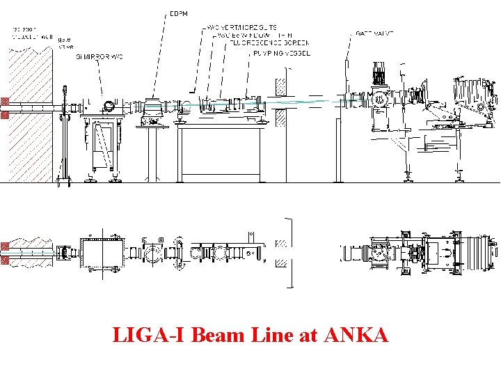
LIGA-I Beam Line at ANKA
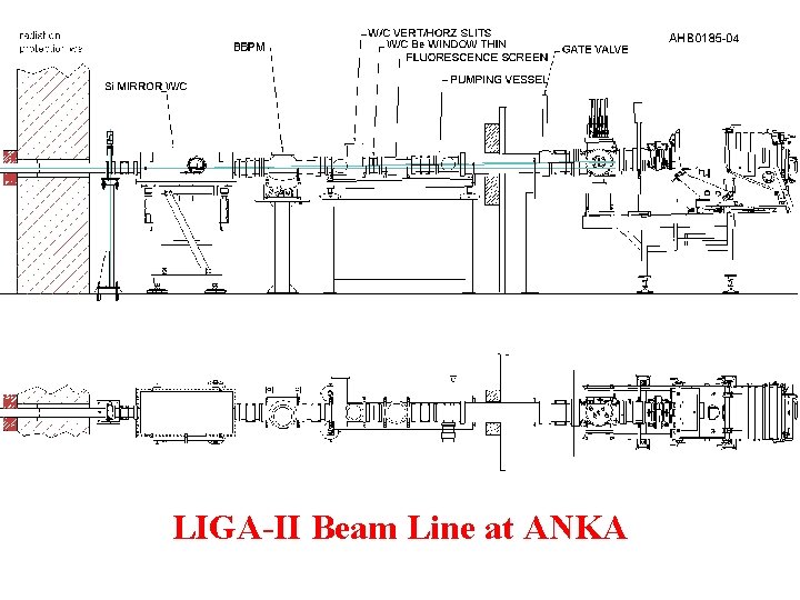
LIGA-II Beam Line at ANKA
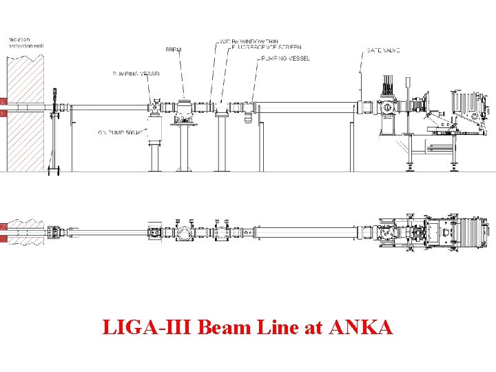
LIGA-III Beam Line at ANKA
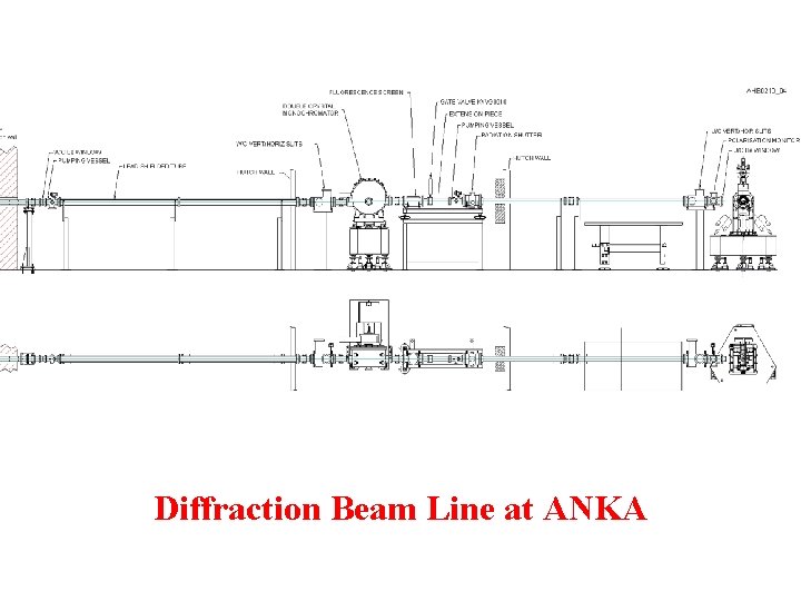
Diffraction Beam Line at ANKA
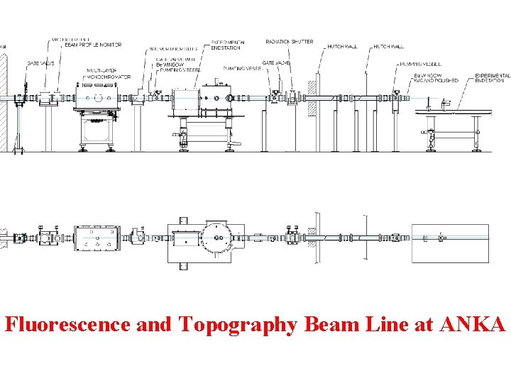
Fluorescence and Topography Beam Line at ANKA
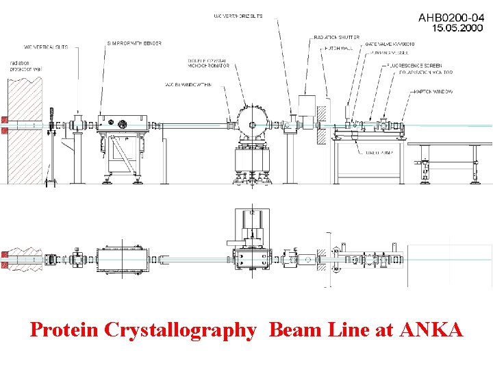
Protein Crystallography Beam Line at ANKA
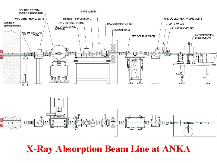
X-Ray Absorption Beam Line at ANKA
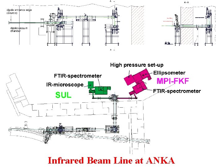
Infrared Beam Line at ANKA
SESAME Synchrotron Radiation Facility E= 2. 0 Gev = 17. 3 nm. rad C= 126 m
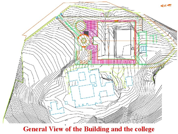
General View of the Building and the college
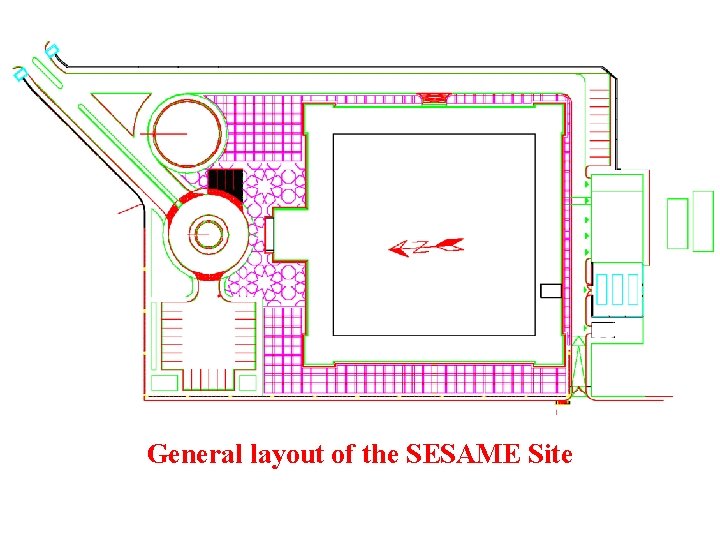
General layout of the SESAME Site
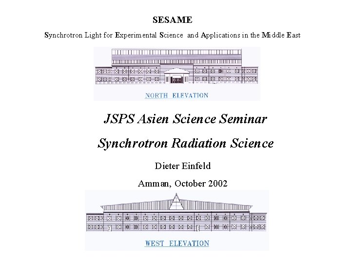
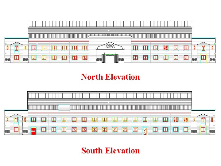
North Elevation South Elevation
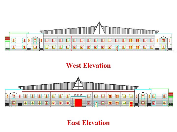
West Elevation East Elevation
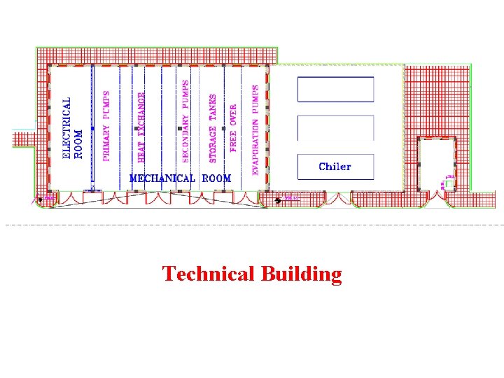
Technical Building
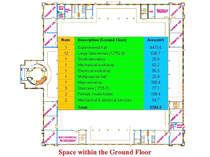
Num Description (Ground Floor) Area (m 2) 1 Experimental hall 4473. 5 12 Large laboratories (12*52, 5) 630. 7 1 Small laboratory 25. 6 1 Mechanical workshop 83. 2 1 Electrical workshop 56. 5 1 Multipurpose hall 25. 4 1 Main entrance 168. 4 3 Staircase ( 3*25. 7) 77. 1 2 Female / male toilets 109. 4 2 Mechanical & electrical services 54. 7 Total: 5704. 5 Space within the Ground Floor
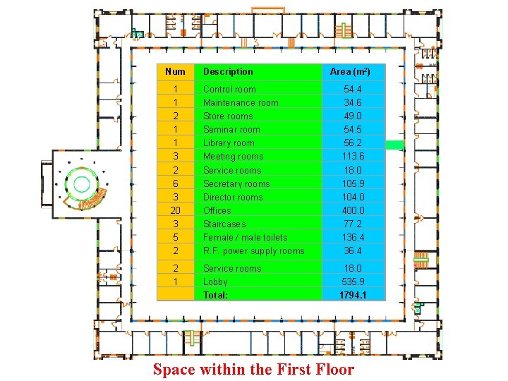
Num Description Area (m 2) 1 1 2 1 1 3 2 6 3 20 3 5 2 Control room Maintenance room Store rooms Seminar room Library room Meeting rooms Service rooms Secretary rooms Director rooms Offices Staircases Female / male toilets R. F. power supply rooms 54. 4 34. 6 49. 0 54. 5 56. 2 113. 6 18. 0 105. 9 104. 0 400. 0 77. 2 136. 4 2 1 Service rooms Lobby Total: 18. 0 535. 9 1794. 1 Space within the First Floor
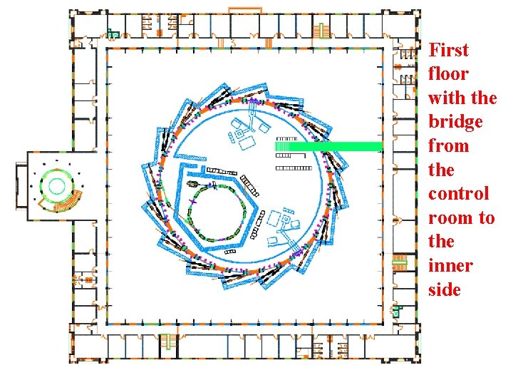
First floor with the bridge from the control room to the inner side