
Lattice Design PSI Synchrotron Beam Dynamics Group SLS

Lattice Design PSI Synchrotron Beam Dynamics Group SLS 2. 0 Lattice Review Meeting PSI, March 5 -6, 2020
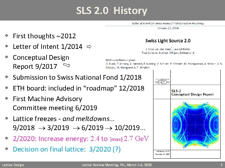
SLS 2. 0 History w First thoughts 2012 w Letter of Intent 1/2014 w Conceptual Design Report 9/2017 w Submission to Swiss National Fond 1/2018 w ETH board: included in “roadmap” 12/2018 w First Machine Advisory Committee meeting 6/2019 w Lattice freezes - and meltdowns. . . 9/2018 3/2019 6/2019 10/2019. . . w 2/2020: Increase energy: 2. 4 to [max] 2. 7 Ge. V w Decision on final lattice: 3/2020 (? ) Lattice Design Lattice Review Meeting, PSI, March 5 -6, 2020 2
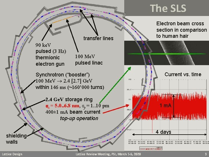
The SLS transfer lines 90 ke. V pulsed (3 Hz) thermionic electron gun 100 Me. V pulsed linac Synchrotron (“booster”) 100 Me. V 2. 4 [2. 7] Ge. V within 146 ms (~160’ 000 turns) 2. 4 Ge. V storage ring ex = 5. 0. . 6. 8 nm, ey = 1. . 10 pm 400± 1 m. A beam current top-up operation Current vs. time 1 m. A 4 days shielding walls Lattice Design Electron beam cross section in comparison to human hair Lattice Review Meeting, PSI, March 5 -6, 2020 3
SLS parameters and features w Lattice type w circumference w Straights w w w w Superbends Energy Emittance Energy spread Current Beam Lifetime Lattice version Lattice Design 12 × 3 BA, no combined functions 288 m 6 × 4. 0 m, bx/by = 1. 4/1. 0 m 3 × 7. 0 m, 3 × 11. 7 m 3 × 2. 9 T 2. 411 Ge. V [ 2. 7 Ge. V] 5630 pm 0. 878 10 -3 400 m. A [250 m. A at 2. 7 Ge. V] 8 hrs sls_f 6 cwo_bxs Lattice Review Meeting, PSI, March 5 -6, 2020 4
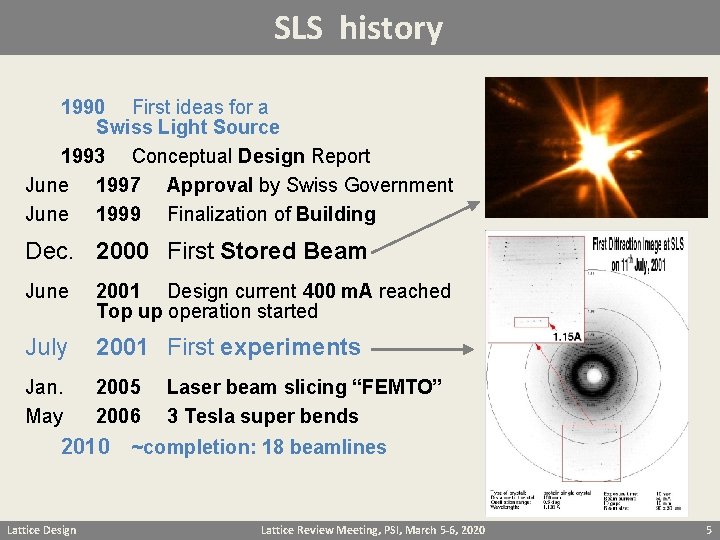
SLS history 1990 First ideas for a Swiss Light Source 1993 Conceptual Design Report June 1997 Approval by Swiss Government June 1999 Finalization of Building Dec. 2000 First Stored Beam June 2001 Design current 400 m. A reached Top up operation started July 2001 First experiments Jan. May 2005 2006 Laser beam slicing “FEMTO” 3 Tesla super bends 2010 ~completion: 18 beamlines Lattice Design Lattice Review Meeting, PSI, March 5 -6, 2020 5
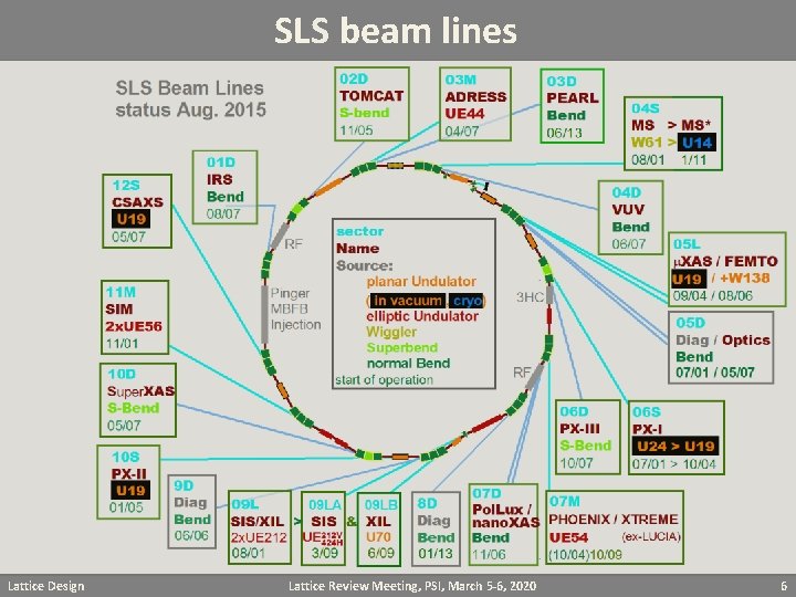
SLS beam lines Lattice Design Lattice Review Meeting, PSI, March 5 -6, 2020 6
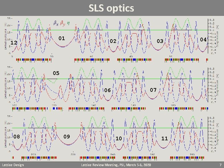
SLS optics 12 01 02 03 04 05 07 06 08 Lattice Design 09 10 Lattice Review Meeting, PSI, March 5 -6, 2020 11 7
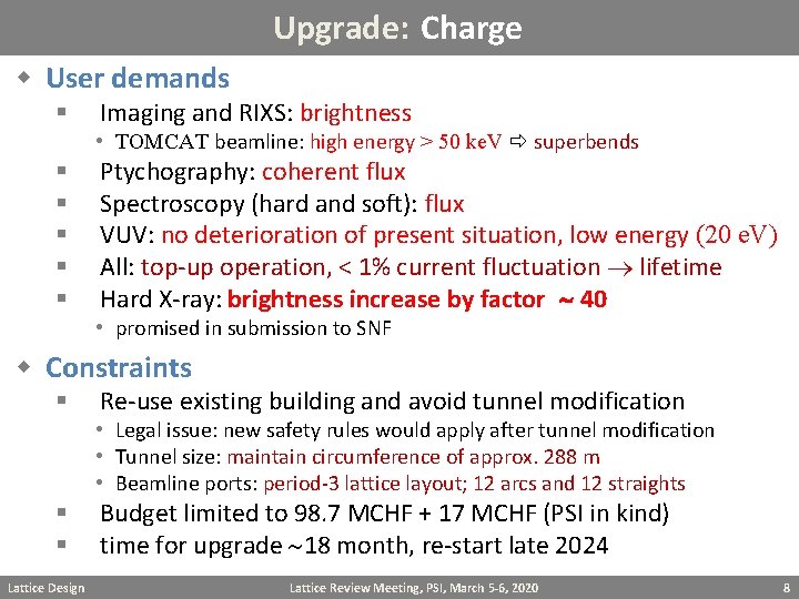
Upgrade: Charge w User demands § Imaging and RIXS: brightness • TOMCAT beamline: high energy > 50 ke. V superbends § § § Ptychography: coherent flux Spectroscopy (hard and soft): flux VUV: no deterioration of present situation, low energy (20 e. V) All: top-up operation, < 1% current fluctuation lifetime Hard X-ray: brightness increase by factor 40 • promised in submission to SNF w Constraints § Re-use existing building and avoid tunnel modification • Legal issue: new safety rules would apply after tunnel modification • Tunnel size: maintain circumference of approx. 288 m • Beamline ports: period-3 lattice layout; 12 arcs and 12 straights § § Lattice Design Budget limited to 98. 7 MCHF + 17 MCHF (PSI in kind) time for upgrade 18 month, re-start late 2024 Lattice Review Meeting, PSI, March 5 -6, 2020 8
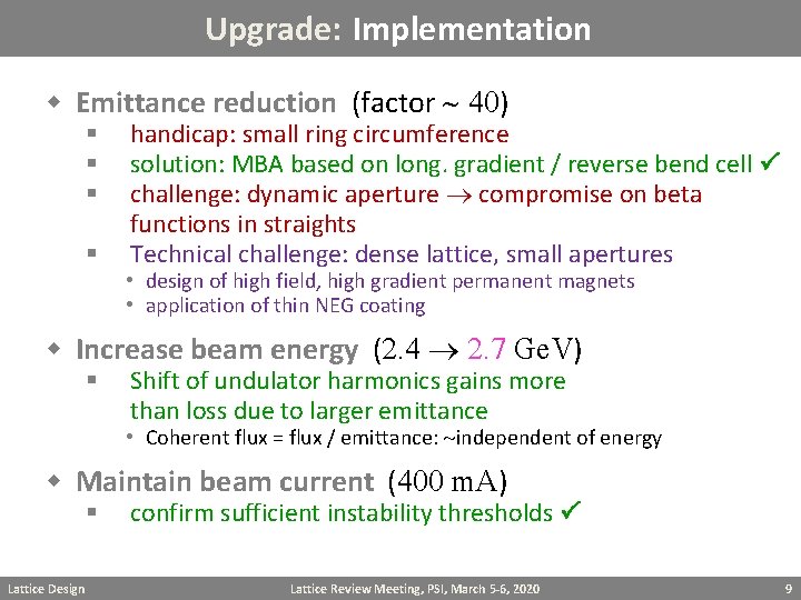
Upgrade: Implementation w Emittance reduction (factor 40) § § handicap: small ring circumference solution: MBA based on long. gradient / reverse bend cell challenge: dynamic aperture compromise on beta functions in straights Technical challenge: dense lattice, small apertures • design of high field, high gradient permanent magnets • application of thin NEG coating w Increase beam energy (2. 4 2. 7 Ge. V) § Shift of undulator harmonics gains more than loss due to larger emittance • Coherent flux = flux / emittance: independent of energy w Maintain beam current (400 m. A) § Lattice Design confirm sufficient instability thresholds Lattice Review Meeting, PSI, March 5 -6, 2020 9
Upgrade: Implementation w New undulators § § increase length ( 4 m), reduce period hard X-ray ( 5 - 30 ke. V): planar, gap 4 ( 3 ? ) mm; period 19, 15 ( 10? ) mm • MBA: small beam pipe narrow poles, low forces coupling control to avoid vertical Touschek losses § soft X-ray: round bore ( 8 mm) Apple-X undulators, 35 mm period • cover 200 e. V – 2 ke. V on fundamental (circular polarization) round bore requires careful design of injection scheme long undulators require >5 m straight sections Lattice Design Lattice Review Meeting, PSI, March 5 -6, 2020 10
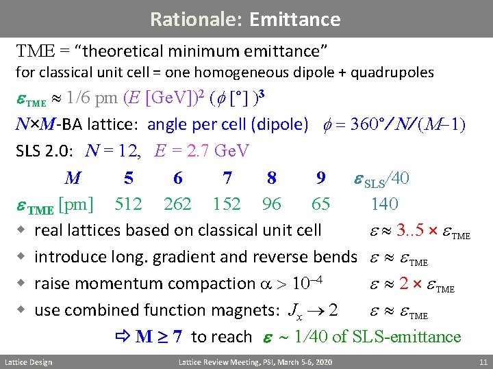
Rationale: Emittance TME = “theoretical minimum emittance” for classical unit cell = one homogeneous dipole + quadrupoles e TME 1/6 pm (E [Ge. V])2 (f [°] )3 N×M-BA lattice: angle per cell (dipole) f = 360°/ N/ (M-1) SLS 2. 0: N = 12, E = 2. 7 Ge. V M 5 6 7 8 9 e SLS/40 e TME [pm] 512 262 152 96 65 140 w real lattices based on classical unit cell e 3. . 5 × e TME w introduce long. gradient and reverse bends e e TME w raise momentum compaction a > 10 -4 e 2 × e TME w use combined function magnets: Jx 2 e e TME M 7 to reach e 1/40 of SLS-emittance Lattice Design Lattice Review Meeting, PSI, March 5 -6, 2020 11
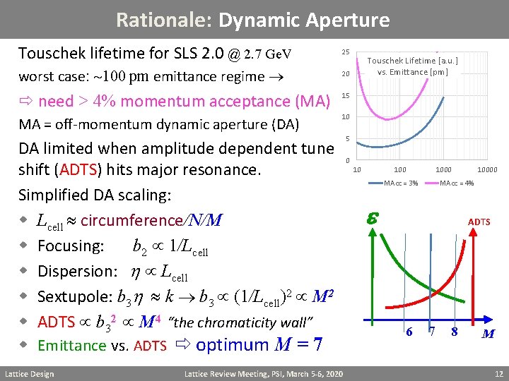
Rationale: Dynamic Aperture Touschek lifetime for SLS 2. 0 @ 2. 7 Ge. V 25 worst case: 100 pm emittance regime 20 need > 4% momentum acceptance (MA) 15 MA = off-momentum dynamic aperture (DA) 10 DA limited when amplitude dependent tune shift (ADTS) hits major resonance. Simplified DA scaling: w Lcell circumference/N/M w Focusing: b 2 1/Lcell w Dispersion: h Lcell w Sextupole: b 3 h k b 3 (1/Lcell)2 M 2 w ADTS b 32 M 4 “the chromaticity wall” w Emittance vs. ADTS optimum M = 7 Lattice Design Lattice Review Meeting, PSI, March 5 -6, 2020 Touschek Lifetime [a. u. ] vs. Emittance [pm] 5 0 10 1000 MAcc = 3% 10000 MAcc = 4% e ADTS 6 7 8 M 12
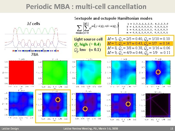
Periodic MBA : multi-cell cancellation M cells 7 BA Lattice Design Sextupole and octupole Hamiltonian modes M-1 j k l m = = 2, 3, 1, 1, 1, 2, 0, 1, 0, 0, 1, 0, 2, 0, 0, 1, 2, 0, 0, 0, 4, 2, 2, 3, 0 0, 0, 0, 1, 0 0, 2, 0, 0, 3 0, 0, 2, 0, 1 Light source cell M = 5, Qx = 2/5 = 0. 40, Qy = 1/10 = 0. 10 Qx high (> 0. 4) M = 7, Qx = 3/7 0. 43, Qy = 1/7 0. 14 Qy low ( 0. 1) M = 8, Qx = 3/8 0. 38, Qy = 1/16 0. 06 M = 9, Qx = 4/9 0. 44, Qy = 1/9 0. 11 Lattice Review Meeting, PSI, March 5 -6, 2020 13
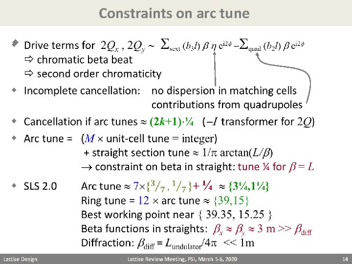
Constraints on arc tune w Lattice Design Lattice Review Meeting, PSI, March 5 -6, 2020 14
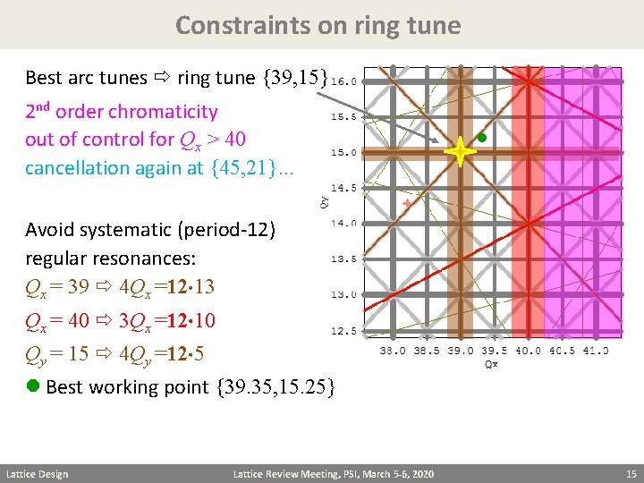
Constraints on ring tune Best arc tunes ring tune {39, 15} 2 nd order chromaticity out of control for Qx > 40 cancellation again at {45, 21}. . . Avoid systematic (period-12) regular resonances: Qx = 39 4 Qx =12 13 Qx = 40 3 Qx =12 10 Qy = 15 4 Qy =12 5 Best working point {39. 35, 15. 25} Lattice Design Lattice Review Meeting, PSI, March 5 -6, 2020 15
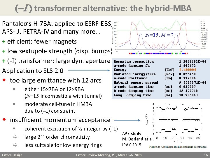
(-I ) transformer alternative: the hybrid-MBA Pantaleo’s H-7 BA: applied to ESRF-EBS, APS-U, PETRA-IV and many more. . . N =15, M = 7 + efficient: fewer magnets + low sextupole strength (disp. bumps) + (-I) transformer: large dyn. aperture Momentum compaction a-mode damping Ja Energy [Ge. V] Application to SLS 2. 0 Radiated energy/turn [Me. V] a-mode Emittance [nm] w too large emittance with 12 arcs Natural energy spread § § either 15× 7 BA or 12× 9 BA (N=15 incompatible with tunnel) moderate cell-tune in HMBA due to (–I) constraint a-mode damping time b-mode damping time Long. damping time [ms] 1. 1089492 E-04 1. 840672 2. 400000 0. 025450 0. 132986 9. 6097371 E-04 6. 617007 12. 179740 10. 505863 w insufficient momentum acceptance § Lattice Design coherent excitation of ½-integer by (–I) large 2 nd order chromaticity less suitable for low energy rings APS-study M. Borland et al. IPAC 2015 Lattice Review Meeting, PSI, March 5 -6, 2020 16
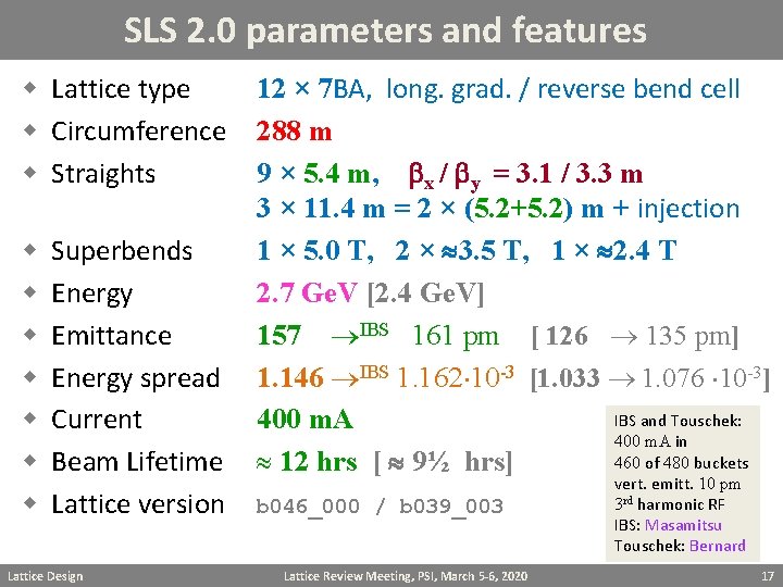
SLS 2. 0 parameters and features w Lattice type w Circumference w Straights w w w w Superbends Energy Emittance Energy spread Current Beam Lifetime Lattice version Lattice Design 12 × 7 BA, long. grad. / reverse bend cell 288 m 9 × 5. 4 m, bx / by = 3. 1 / 3. 3 m 3 × 11. 4 m = 2 × (5. 2+5. 2) m + injection 1 × 5. 0 T, 2 × 3. 5 T, 1 × 2. 4 T 2. 7 Ge. V [2. 4 Ge. V] 157 IBS 161 pm [ 126 135 pm] 1. 146 IBS 1. 162 10 -3 [1. 033 1. 076 10 -3] IBS and Touschek: 400 m. A in 460 of 480 buckets 12 hrs [ 9½ hrs] b 046_000 / b 039_003 Lattice Review Meeting, PSI, March 5 -6, 2020 vert. emitt. 10 pm 3 rd harmonic RF IBS: Masamitsu Touschek: Bernard 17
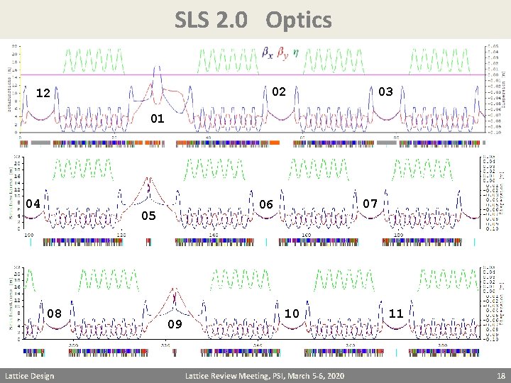
SLS 2. 0 Optics 02 12 03 01 04 05 08 Lattice Design 07 06 09 10 Lattice Review Meeting, PSI, March 5 -6, 2020 11 18
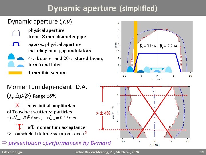
Dynamic aperture (simplified) Dynamic aperture (x, y) physical aperture from 18 mm diameter pipe approx. physical aperture including mini-gap undulators bx = 17 m by = 7. 2 m 4 -s booster and 20 -s stored beam, turn 0 and later 1 mm thin septum Momentum dependent. D. A. (x, Dp/p) Range 6% max. initial amplitudes of Touschek scattered particles = (Hmax b ½ x) Dp/p , Hmax 0. 47 mm > 4% eff. momentum acceptance Touschek- Lifetime (mom. acc. ) 3 presentation «performance» by Bernard Lattice Design Lattice Review Meeting, PSI, March 5 -6, 2020 19
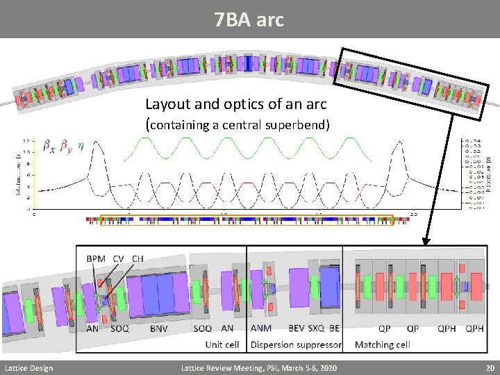
7 BA arc Layout and optics of an arc (containing a central superbend) Lattice Design Lattice Review Meeting, PSI, March 5 -6, 2020 20
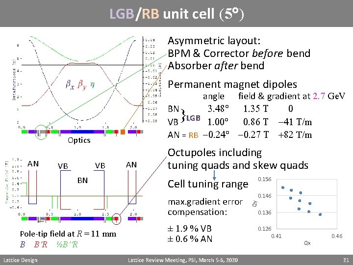
LGB/RB unit cell (5 ) Asymmetric layout: BPM & Corrector before bend Absorber after bend Permanent magnet dipoles angle field & gradient at 2. 7 Ge. V BN 3. 48 1. 35 T 0 VB LGB 1. 00 0. 86 T -41 T/m AN = RB -0. 24 -0. 27 T +82 T/m } AN VB VB BN Pole-tip field at R = 11 mm B B R ½B R Lattice Design AN Octupoles including tuning quads and skew quads Cell tuning range 0. 156 max. gradient error compensation: 0. 146 ± 1. 9 % VB ± 0. 6 % AN Lattice Review Meeting, PSI, March 5 -6, 2020 Qy Optics 0. 136 0. 126 0. 41 Qx 0. 46 21
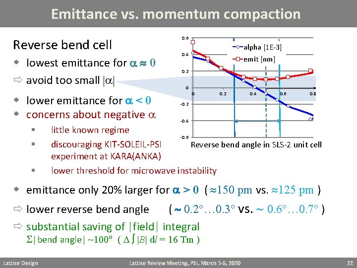
Emittance vs. momentum compaction 0. 6 Reverse bend cell w lowest emittance for a 0 avoid too small |a| w lower emittance for a < 0 w concerns about negative a § § § alpha [1 E-3] 0. 4 emit [nm] 0. 2 0 0 0. 2 0. 4 0. 6 0. 8 -0. 2 -0. 4 little known regime -0. 6 discouraging KIT-SOLEIL-PSI Reverse bend angle in SLS-2 unit cell experiment at KARA(ANKA) lower threshold for microwave instability w emittance only 20% larger for a > 0 ( 150 pm vs. 125 pm ) lower reverse bend angle ( 0. 2 … 0. 3 vs. 0. 6 … 0. 7 ) substantial saving of |field| integral S|bend angle| 100 ( D |B| dl = 16 Tm ) Lattice Design Lattice Review Meeting, PSI, March 5 -6, 2020 22
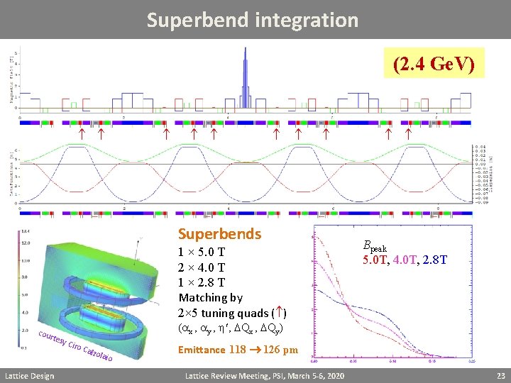
Superbend integration (2. 4 Ge. V) Superbends 1 × 5. 0 T 2 × 4. 0 T 1 × 2. 8 T Matching by 2× 5 tuning quads ( ) cou rt esy Lattice Design Bpeak 5. 0 T, 4. 0 T, 2. 8 T (ax , ay , h , DQx , DQy) Ciro Cal zola io Emittance 118 126 pm Lattice Review Meeting, PSI, March 5 -6, 2020 23
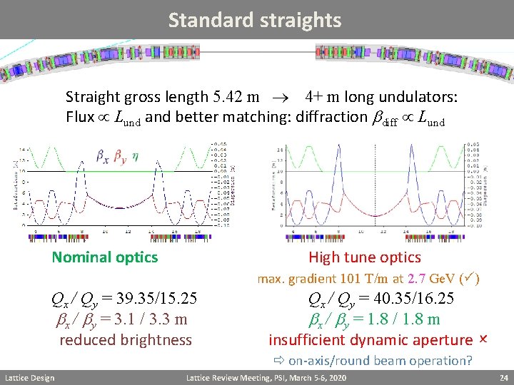
Standard straights Straight gross length 5. 42 m 4+ m long undulators: Flux Lund and better matching: diffraction bdiff Lund Nominal optics High tune optics max. gradient 101 T/m at 2. 7 Ge. V ( ) Qx / Qy = 39. 35/15. 25 bx / by = 3. 1 / 3. 3 m reduced brightness Lattice Design Qx / Qy = 40. 35/16. 25 bx / by = 1. 8 / 1. 8 m insufficient dynamic aperture on-axis/round beam operation? Lattice Review Meeting, PSI, March 5 -6, 2020 24
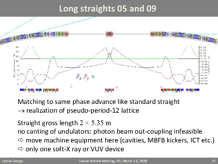
Long straights 05 and 09 Matching to same phase advance like standard straight realization of pseudo-period-12 lattice Straight gross length 2 × 5. 35 m no canting of undulators: photon beam out-coupling infeasible move machine equipment here (cavities, MBFB kickers, ICT etc. ) only one soft-X ray or VUV device Lattice Design Lattice Review Meeting, PSI, March 5 -6, 2020 25
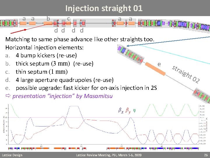
Injection straight 01 a a c b d d a a d d Matching to same phase advance like other straights too. Horizontal injection elements: a. 4 bump kickers (re-use) b. thick septum (3 mm) (re-use) e c. thin septum (1 mm) d. 4 large aperture quadrupoles (re-use) e. possible upgrade: fast kicker for on-axis injection in 2 S presentation “injection” by Masamitsu Lattice Design Lattice Review Meeting, PSI, March 5 -6, 2020 str aig h t 0 2 26
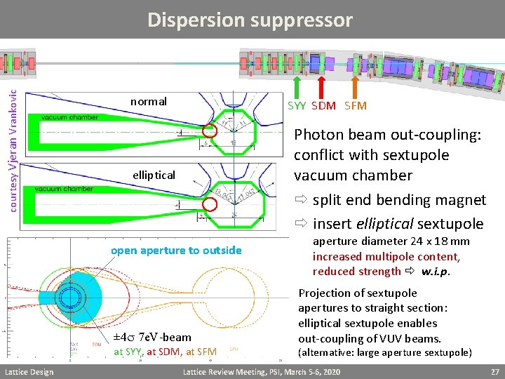
courtesy Vjeran Vrankovic Dispersion suppressor normal SYY SDM SFM Photon beam out-coupling: conflict with sextupole vacuum chamber split end bending magnet insert elliptical sextupole elliptical open aperture to outside ± 4 s 7 e. V-beam at SYY, at SDM, at SFM Lattice Design aperture diameter 24 x 18 mm increased multipole content, reduced strength w. i. p. Projection of sextupole apertures to straight section: elliptical sextupole enables out-coupling of VUV beams. (alternative: large aperture sextupole) Lattice Review Meeting, PSI, March 5 -6, 2020 27
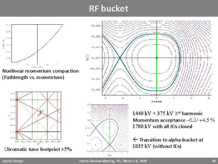
RF bucket Nonlinear momentum compaction (Pathlength vs. momentum) 1440 k. V + 375 k. V 3 rd harmonic Momentum acceptance -6. 2/ +4. 5 % 1780 k. V with all IDs closed Chromatic tune footprint ± 5% Lattice Design Transition to alpha-bucket at 1835 k. V (without IDs) Lattice Review Meeting, PSI, March 5 -6, 2020 28
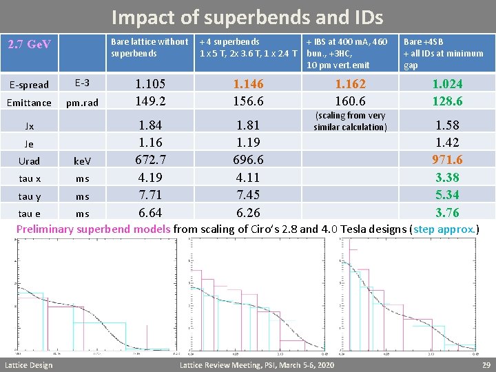
Impact of superbends and IDs Bare lattice without + 4 superbends 1 x 5 T, 2 x 3. 6 T, 1 x 2. 4 T 2. 7 Ge. V E-spread E-3 Emittance pm. rad Jx Je Urad ke. V tau x ms tau y ms tau e ms 1. 105 149. 2 1. 84 1. 16 672. 7 4. 19 7. 71 6. 64 + IBS at 400 m. A, 460 bun. , +3 HC, 10 pm vert. emit Bare +4 SB + all IDs at minimum gap 1. 162 160. 6 1. 024 128. 6 1. 146 156. 6 1. 81 1. 19 696. 6 4. 11 7. 45 6. 26 (scaling from very similar calculation) 1. 58 1. 42 971. 6 3. 38 5. 34 3. 76 Preliminary superbend models from scaling of Ciro’s 2. 8 and 4. 0 Tesla designs (step approx. ) Lattice Design Lattice Review Meeting, PSI, March 5 -6, 2020 29
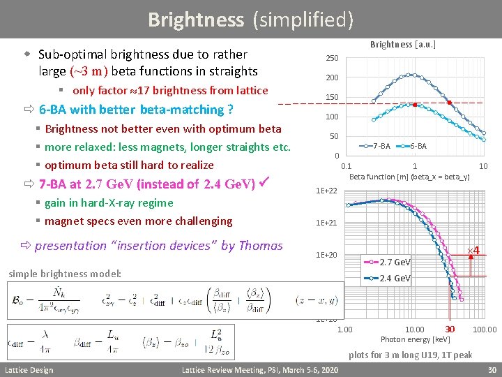
Brightness (simplified) w Sub-optimal brightness due to rather large (~3 m) beta functions in straights § only factor 17 brightness from lattice 6 -BA with better beta-matching ? § Brightness not better even with optimum beta § more relaxed: less magnets, longer straights etc. § optimum beta still hard to realize 7 -BA at 2. 7 Ge. V (instead of 2. 4 Ge. V) § gain in hard-X-ray regime § magnet specs even more challenging presentation “insertion devices” by Thomas Brightness [a. u. ] 250 200 150 100 50 7 -BA 0 6 -BA 0. 1 1 Beta function [m] (beta_x = beta_y) 10 1 E+22 1 E+21 1 E+20 2. 7 Ge. V simple brightness model: × 4 2. 4 Ge. V 1 E+19 1 E+18 1. 00 10. 00 30 Photon energy [ke. V] 100. 00 plots for 3 m long U 19, 1 T peak Lattice Design Lattice Review Meeting, PSI, March 5 -6, 2020 30
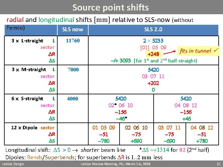
Source point shifts radial and longitudinal shifts [mm] relative to SLS-now (without Femto) SLS now 3 L-straight L sector DR DS 11760 3 M-straight L sector DR DS 7000 6 S-straight L sector DR DS 4000 12 Dipole sector DR DS SLS 2. 0 2 × 5235 [01] 05 09 fits in tunnel +248 -/+ 3093 (for 1 st and 2 nd half-straight) 5420 03 07 11 +202 0 5420 02* 06 10 -156 -46* 01 05 09 -51 -780 02 06 10 -75 +690 5420 04 08 12 -156 +46 03 07 11 -75 -690 04 08 12 -51 +780 Longitudinal shift: DS > 0 shorter beam line *DS =+1314 for 02 (2 nd half) Dipoles: Bends/Superbends; for superbends DR is 1. . 2 mm less Lattice Design Lattice Review Meeting, PSI, March 5 -6, 2020 31
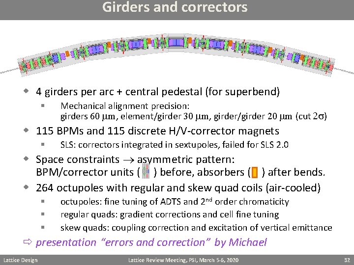
Girders and correctors w 4 girders per arc + central pedestal (for superbend) § Mechanical alignment precision: girders 60 mm, element/girder 30 mm, girder/girder 20 mm (cut 2 s) w 115 BPMs and 115 discrete H/V-corrector magnets § SLS: correctors integrated in sextupoles, failed for SLS 2. 0 w Space constraints asymmetric pattern: BPM/corrector units ( ) before, absorbers ( ) after bends. w 264 octupoles with regular and skew quad coils (air-cooled) § § § octupoles: fine tuning of ADTS and 2 nd order chromaticity regular quads: gradient corrections and cell fine tuning skew quads: coupling correction and excitation of vertical emittance presentation “errors and correction” by Michael Lattice Design Lattice Review Meeting, PSI, March 5 -6, 2020 32
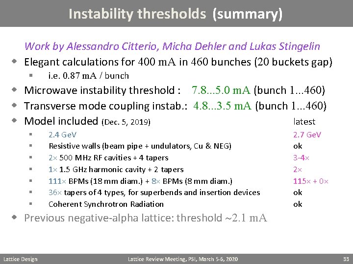
Instability thresholds (summary) Work by Alessandro Citterio, Micha Dehler and Lukas Stingelin w Elegant calculations for 400 m. A in 460 bunches (20 buckets gap) § i. e. 0. 87 m. A / bunch w Microwave instability threshold : 7. 8. . . 5. 0 m. A (bunch 1. . . 460) w Transverse mode coupling instab. : 4. 8. . . 3. 5 m. A (bunch 1. . . 460) w Model included (Dec. 5, 2019) latest § § § § 2. 4 Ge. V Resistive walls (beam pipe + undulators, Cu & NEG) 2× 500 MHz RF cavities + 4 tapers 1× 1. 5 GHz harmonic cavity + 2 tapers 111× BPMs (18 mm diam. ) + 8× BPMs (8 mm diam. ) 36× tapers of 4 types, for superbends and insertion devices Coherent Synchrotron Radiation 2. 7 Ge. V ok 3 -4× 2× 115× + 0× ok ok w Previous negative-alpha lattice: threshold 2. 1 m. A Lattice Design Lattice Review Meeting, PSI, March 5 -6, 2020 33
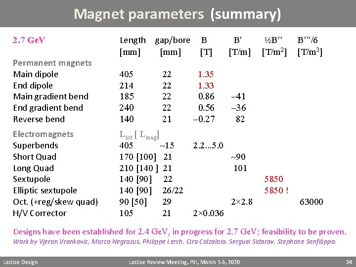
Magnet parameters (summary) 2. 7 Ge. V Length [mm] gap/bore B [mm] [T] Permanent magnets Main dipole End dipole Main gradient bend End gradient bend Reverse bend 405 214 185 240 140 Electromagnets Superbends Short Quad Long Quad Sextupole Elliptic sextupole Oct. (+reg/skew quad) H/V Corrector Ltot [ Lmag] 405 15 170 [100] 21 210 [140 ] 21 140 [90] 22 140 [90] 26/22 90 [50] 29 105 21 22 22 21 1. 35 1. 33 0. 86 0. 56 -0. 27 2. 2. . . 5. 0 B [T/m] ½B [T/m 2] B /6 [T/m 3] -41 -36 82 90 101 5850 ! 2× 2. 8 63000 2× 0. 036 Designs have been established for 2. 4 Ge. V, in progress for 2. 7 Ge. V; feasibility to be proven. Work by Vjeran Vrankovic, Marco Negrazus, Philippe Lerch, Ciro Calzolaio, Serguei Sidorov, Stephane Sanfilippo. Lattice Design Lattice Review Meeting, PSI, March 5 -6, 2020 34
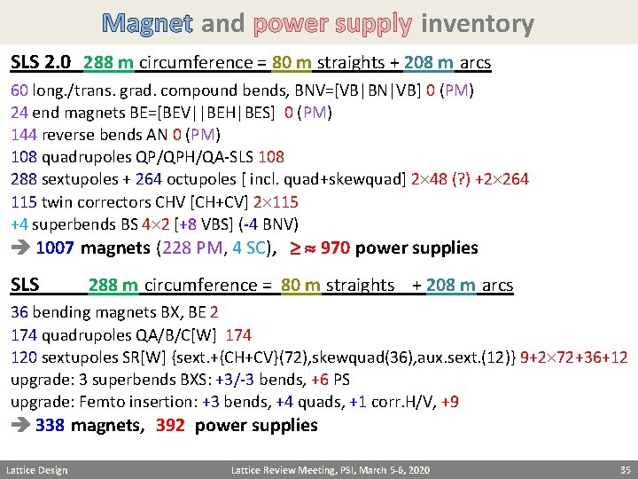
Magnet and power supply inventory SLS 2. 0 288 m circumference = 80 m straights + 208 m arcs 60 long. /trans. grad. compound bends, BNV=[VB|BN|VB] 0 (PM) 24 end magnets BE=[BEV||BEH|BES] 0 (PM) 144 reverse bends AN 0 (PM) 108 quadrupoles QP/QPH/QA-SLS 108 288 sextupoles + 264 octupoles [ incl. quad+skewquad] 2 48 (? ) +2 264 115 twin correctors CHV [CH+CV] 2 115 +4 superbends BS 4 2 [+8 VBS] (-4 BNV) 1007 magnets (228 PM, 4 SC), 970 power supplies SLS 288 m circumference = 80 m straights + 208 m arcs 36 bending magnets BX, BE 2 174 quadrupoles QA/B/C[W] 174 120 sextupoles SR[W] {sext. +{CH+CV}(72), skewquad(36), aux. sext. (12)} 9+2 72+36+12 upgrade: 3 superbends BXS: +3/-3 bends, +6 PS upgrade: Femto insertion: +3 bends, +4 quads, +1 corr. H/V, +9 338 magnets, 392 power supplies Lattice Design Lattice Review Meeting, PSI, March 5 -6, 2020 35
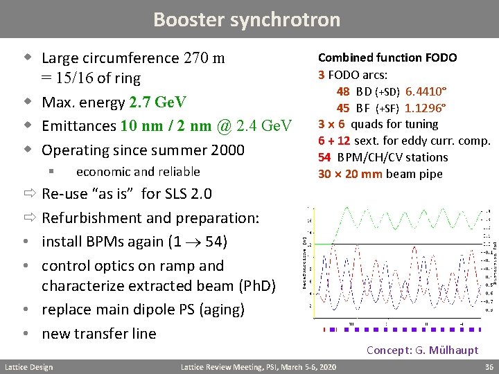
Booster synchrotron w Large circumference 270 m = 15/16 of ring w Max. energy 2. 7 Ge. V w Emittances 10 nm / 2 nm @ 2. 4 Ge. V w Operating since summer 2000 § economic and reliable Combined function FODO 3 FODO arcs: 48 BD (+SD) 6. 4410° 45 BF (+SF) 1. 1296° 3 6 quads for tuning 6 + 12 sext. for eddy curr. comp. 54 BPM/CH/CV stations 30 20 mm beam pipe Re-use “as is” for SLS 2. 0 Refurbishment and preparation: • install BPMs again (1 54) • control optics on ramp and characterize extracted beam (Ph. D) • replace main dipole PS (aging) • new transfer line Lattice Design Lattice Review Meeting, PSI, March 5 -6, 2020 Concept: G. Mülhaupt 36
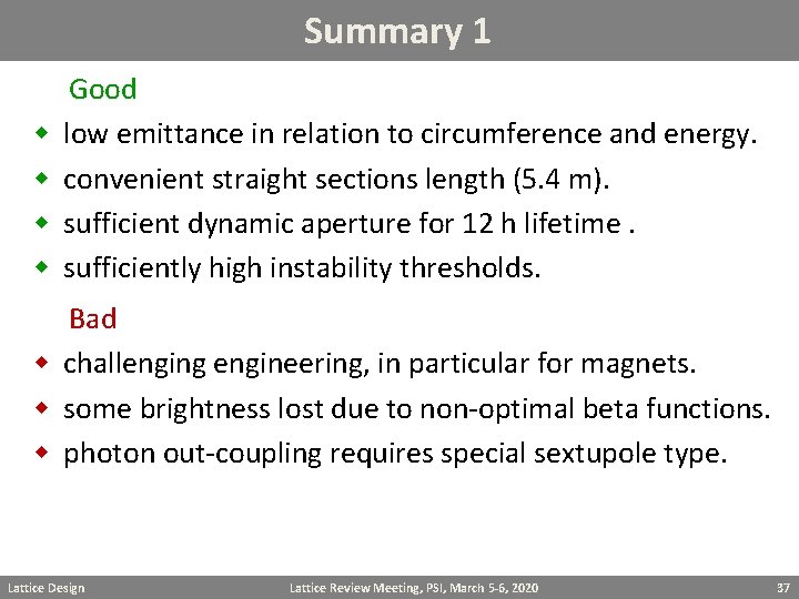
Summary 1 Good w low emittance in relation to circumference and energy. w convenient straight sections length (5. 4 m). w sufficient dynamic aperture for 12 h lifetime. w sufficiently high instability thresholds. Bad w challenging engineering, in particular for magnets. w some brightness lost due to non-optimal beta functions. w photon out-coupling requires special sextupole type. Lattice Design Lattice Review Meeting, PSI, March 5 -6, 2020 37
Summary 2 Questions w lattice type (7 BA, LGB/RB) ? w any counter arguments for 2. 7 Ge. V ? w strategy of brightness optimization ? § § share load between lattice and ID design push IDs and back-off lattice ? w injection scheme ? § push for true on-axis ? w safety margin of impedance models ? w risk estimate for advanced technology ? § Lattice Design PM magnets, spaces, kickers, 500 nm NEG etc. Lattice Review Meeting, PSI, March 5 -6, 2020 38
Back-up Lattice Design Lattice Review Meeting, PSI, March 5 -6, 2020 39
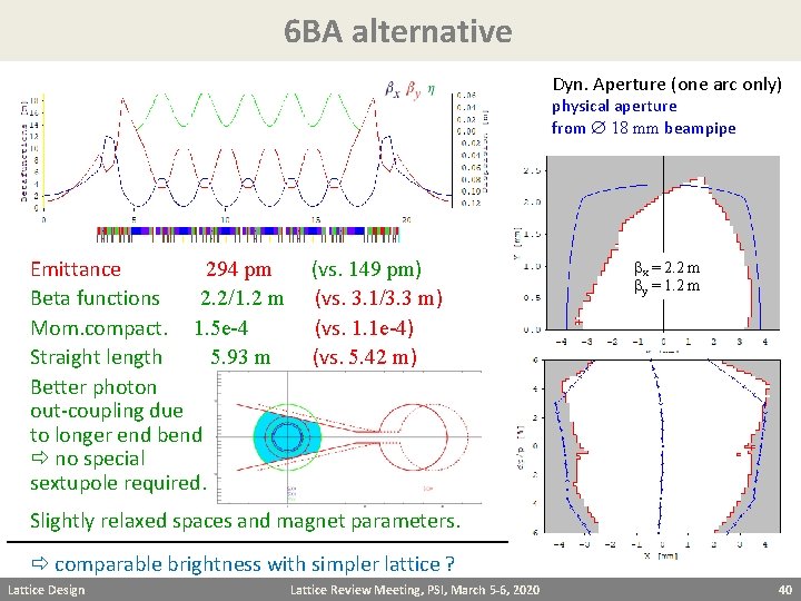
6 BA alternative Dyn. Aperture (one arc only) physical aperture from 18 mm beampipe Emittance 294 pm (vs. 149 pm) Beta functions 2. 2/1. 2 m (vs. 3. 1/3. 3 m) Mom. compact. 1. 5 e-4 (vs. 1. 1 e-4) Straight length 5. 93 m (vs. 5. 42 m) Better photon out-coupling due to longer end bend no special sextupole required. bx = 2. 2 m by = 1. 2 m Slightly relaxed spaces and magnet parameters. comparable brightness with simpler lattice ? Lattice Design Lattice Review Meeting, PSI, March 5 -6, 2020 40
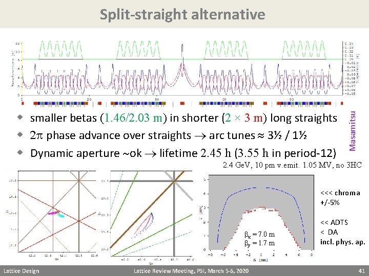
w smaller betas (1. 46/2. 03 m) in shorter (2 × 3 m) long straights w 2 p phase advance over straights arc tunes 3½ / 1½ w Dynamic aperture ok lifetime 2. 45 h (3. 55 h in period-12) Masamitsu Split-straight alternative 2. 4 Ge. V, 10 pm v. emit. 1. 05 MV, no 3 HC <<< chroma +/-5% bx = 7. 0 m by = 1. 7 m Lattice Design Lattice Review Meeting, PSI, March 5 -6, 2020 << ADTS < DA incl. phys. ap. 41
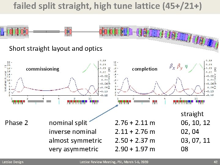
failed split straight, high tune lattice (45+/21+) Short straight layout and optics commissioning Phase 2 Lattice Design completion nominal split inverse nominal almost symmetric very asymmetric 2. 76 + 2. 11 m 2. 11 + 2. 76 m 2. 50 + 2. 37 m 2. 90 + 1. 97 m Lattice Review Meeting, PSI, March 5 -6, 2020 straight 06, 10, 12 02, 04 03, 07, 11 08 42
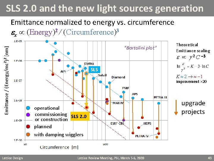
SLS 2. 0 and the new light sources generation Emittance / (Energy/mc 2)2 [nm] Emittance normalized to energy vs. circumference ex (Energy)2 / (Circumference)3 Lattice Design “Bartolini plot” Theoretical Emittance scaling e 2 C -3 SLS K 2 -1 improvement 20 operational commissioning SLS 2. 0 or construction planned with damping wigglers Lattice Review Meeting, PSI, March 5 -6, 2020 upgrade projects 43
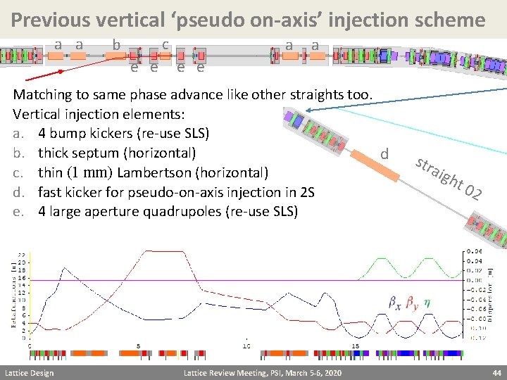
Previous vertical ‘pseudo on-axis’ injection scheme a a c b e e a a e e Matching to same phase advance like other straights too. Vertical injection elements: a. 4 bump kickers (re-use SLS) b. thick septum (horizontal) d c. thin (1 mm) Lambertson (horizontal) d. fast kicker for pseudo-on-axis injection in 2 S e. 4 large aperture quadrupoles (re-use SLS) Lattice Design Lattice Review Meeting, PSI, March 5 -6, 2020 str aig h t 0 2 44
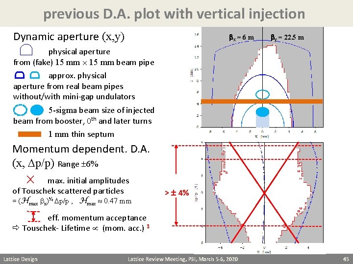
previous D. A. plot with vertical injection Dynamic aperture (x, y) bx = 6 m by = 22. 5 m physical aperture from (fake) 15 mm beam pipe approx. physical aperture from real beam pipes without/with mini-gap undulators 5 -sigma beam size of injected beam from booster, 0 th and later turns 1 mm thin septum Momentum dependent. D. A. (x, Dp/p) Range 6% max. initial amplitudes of Touschek scattered particles = (Hmax bx)½ Dp/p , Hmax 0. 47 mm > 4% eff. momentum acceptance Touschek- Lifetime (mom. acc. ) 3 Lattice Design Lattice Review Meeting, PSI, March 5 -6, 2020 45
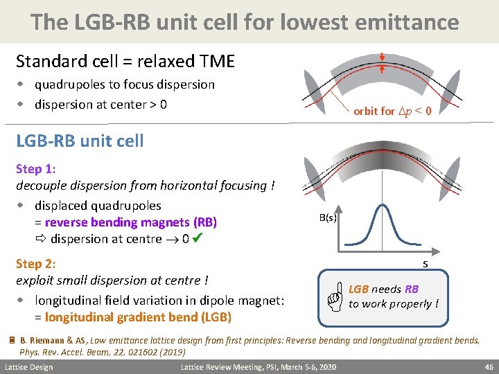
The LGB-RB unit cell for lowest emittance Standard cell = relaxed TME w quadrupoles to focus dispersion w dispersion at center > 0 orbit for Dp < 0 LGB-RB unit cell Step 1: decouple dispersion from horizontal focusing ! w displaced quadrupoles = reverse bending magnets (RB) dispersion at centre 0 Step 2: exploit small dispersion at centre ! w longitudinal field variation in dipole magnet: = longitudinal gradient bend (LGB) B(s) s LGB needs RB to work properly ! B. Riemann & AS, Low emittance lattice design from first principles: Reverse bending and longitudinal gradient bends, Phys. Rev. Accel. Beam, 22, 021602 (2019) Lattice Design Lattice Review Meeting, PSI, March 5 -6, 2020 46
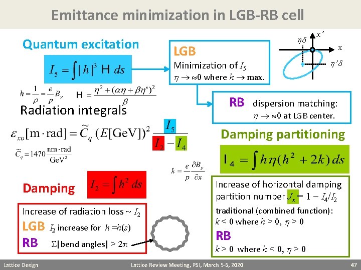
Emittance minimization in LGB-RB cell Quantum excitation hd LGB Minimization of I 5 h 0 where h max. RB Radiation integrals x’ x h ’d dispersion matching: h 0 at LGB center. Damping partitioning Damping Increase of horizontal damping partition number Jx = 1 - I 4/I 2 Increase of radiation loss I 2 traditional (combined function): k < 0 where h > 0, h > 0 LGB I 2 increase for h =h(s) RB S|bend angles| > 2 p Lattice Design RB k > 0 where h < 0, h > 0 Lattice Review Meeting, PSI, March 5 -6, 2020 47
- Slides: 47