Vito Puliafito Magnetism Research Group Universit di Messina
- Slides: 22
Vito Puliafito Magnetism Research Group Università di Messina, Italy Modulazione non lineare di ampiezza e frequenza in nano-oscillatori spintronici XXVI Riunione Annuale dei Ricercatori di Elettrotecnica, ET 2010 9 -11 Giugno 2010, Napoli
Unità di Messina ww 2. unime. it/mrg Componenti o o o o Bruno Azzerboni Alessia Bramanti Andrea Calisto Giancarlo Consolo Giovanni Finocchio Alessandro Prattella Vito Puliafito Principali tematiche di ricerca Modellizzazione materiali magnetici o Micromagnetismo o Spintronica o Elaborazione di segnali biomedicali o Principali collaborazioni: Unità ET di Perugia, prof. Cardelli o Università di Perugia, prof. Carlotti o Università di Ferrara, prof. Nizzoli o Modulazione non lineare di ampiezza e frequenza in nano-oscillatori spintronici Università di Salamanca, Spagna o Università di Cornell, Ithaca, Usa o Università di Oakland, Rochester, Usa o Royal Institute of Technology, Svezia o Vito Puliafito - ET 2010, Napoli, 11/06/2010
Outline n n n Introduction on analog modulation processes Motivation of the present study Mathematical models of modulation Numerical analysis of spintronic nano-oscillators Comparison between analytical, numerical and experimental results Conclusions Modulazione non lineare di ampiezza e frequenza in nano-oscillatori spintronici Vito Puliafito - ET 2010, Napoli, 11/06/2010
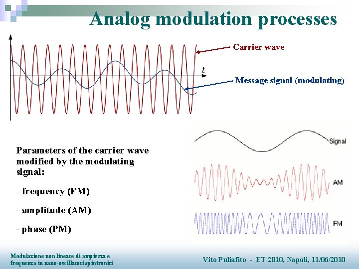
Analog modulation processes Carrier wave Message signal (modulating) Parameters of the carrier wave modified by the modulating signal: - frequency (FM) - amplitude (AM) - phase (PM) Modulazione non lineare di ampiezza e frequenza in nano-oscillatori spintronici Vito Puliafito - ET 2010, Napoli, 11/06/2010
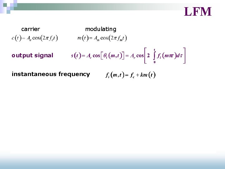
LFM carrier modulating output signal instantaneous frequency spectrum § § § central frequency = fc symmetric sidebands number = ∞
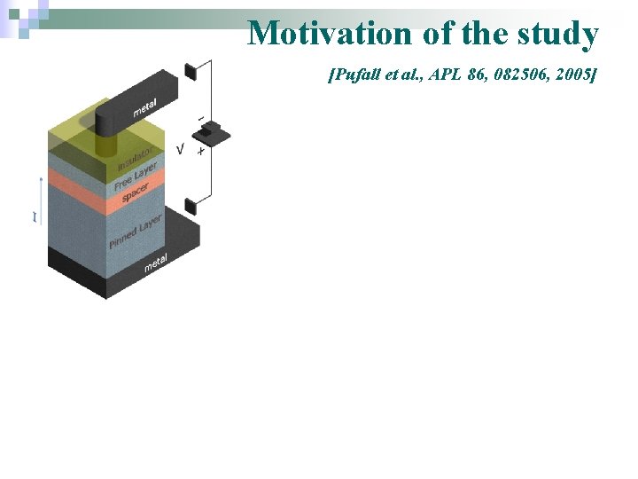
Motivation of the study [Pufall et al. , APL 86, 082506, 2005] § shift of the central frequency § asymmetric sidebands the Spin-Transfer Oscillator (STO) works as a NFM modulator
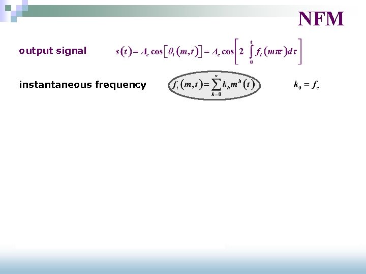
NFM output signal instantaneous frequency § central frequency shift § asymmetric sidebands
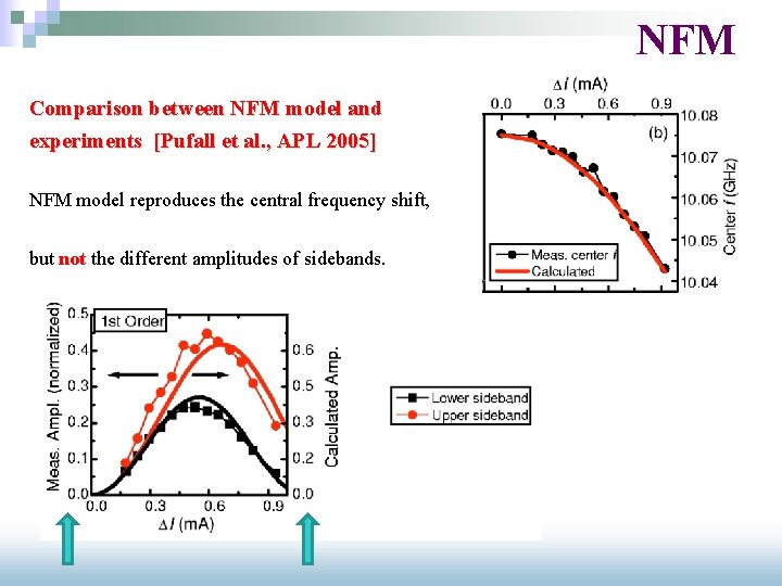
NFM Comparison between NFM model and experiments [Pufall et al. , APL 2005] NFM model reproduces the central frequency shift, but not the different amplitudes of sidebands.
Reason of the disagreement Additive amplitude modulation effects are NOT INCLUDED. There are theoretical, experimental and numerical evidences of amplitude modulation. frequency amplitude [Slavin and Kabos, IEEE Trans. Magn. 41, 2005] [Pufall et al. , APL 2005]
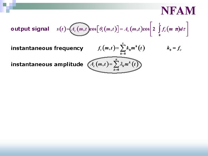
NFAM output signal instantaneous frequency instantaneous amplitude § quantitatively different asymmetric sidebands
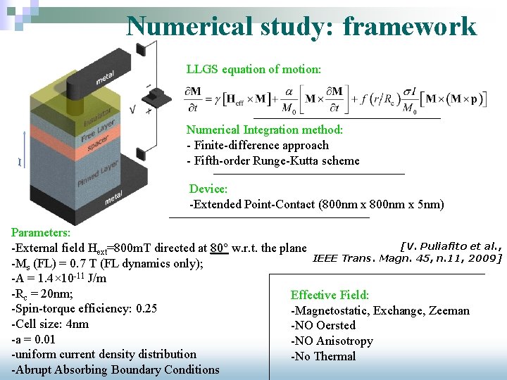
Numerical study: framework LLGS equation of motion: Numerical Integration method: - Finite-difference approach - Fifth-order Runge-Kutta scheme Device: -Extended Point-Contact (800 nm x 5 nm) Parameters: [V. Puliafito et al. , -External field Hext=800 m. T directed at 80° w. r. t. the plane IEEE Trans. Magn. 45, n. 11, 2009] -Ms (FL) = 0. 7 T (FL dynamics only); -A = 1. 4× 10 -11 J/m -Rc = 20 nm; Effective Field: -Spin-torque efficiency: 0. 25 -Magnetostatic, Exchange, Zeeman -Cell size: 4 nm -NO Oersted -a = 0. 01 -NO Anisotropy -uniform current density distribution -No Thermal -Abrupt Absorbing Boundary Conditions
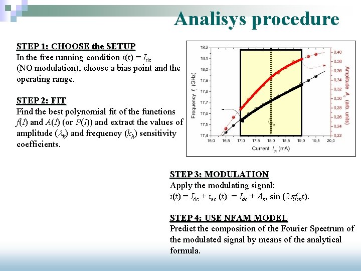
Analisys procedure STEP 1: CHOOSE the SETUP In the free running condition i(t) = Idc (NO modulation), choose a bias point and the operating range. STEP 2: FIT Find the best polynomial fit of the functions f(I) and A(I) (or P(I)) and extract the values of amplitude (lk) and frequency (kh) sensitivity coefficients. STEP 3: MODULATION Apply the modulating signal: i(t) = Idc + iac (t) = Idc + Am sin (2 pfmt). STEP 4: USE NFAM MODEL Predict the composition of the Fourier Spectrum of the modulated signal by means of the analytical formula.
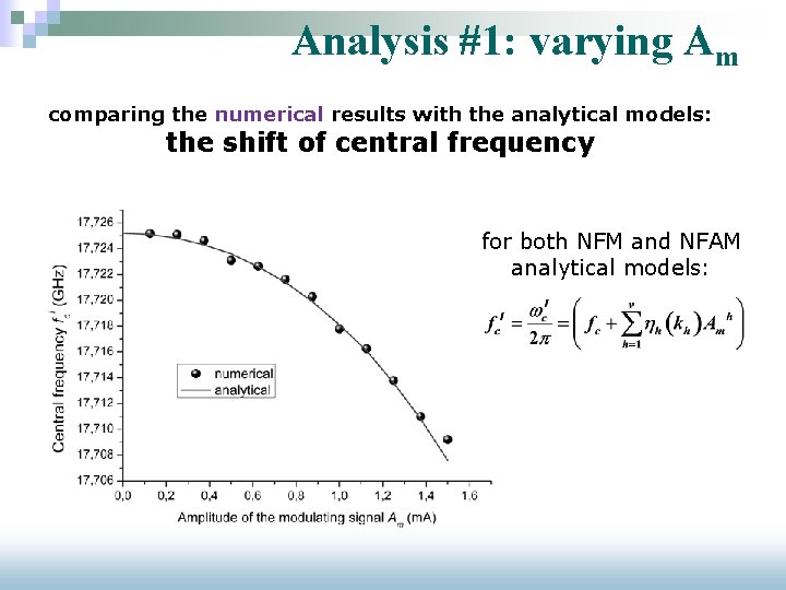
Analysis #1: varying Am comparing the numerical results with the analytical models: the shift of central frequency for both NFM and NFAM analytical models:
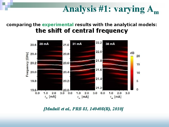
Analysis #1: varying Am comparing the experimental results with the analytical models: the shift of central frequency [Muduli et al. , PRB 81, 140408(R), 2010]
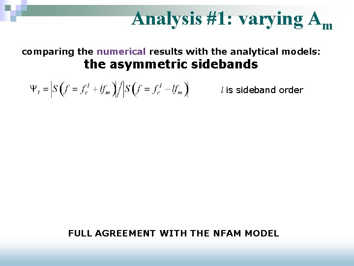
Analysis #1: varying Am comparing the numerical results with the analytical models: the asymmetric sidebands l is sideband order FULL AGREEMENT WITH THE NFAM MODEL
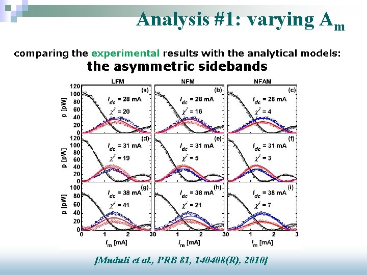
Analysis #1: varying Am comparing the experimental results with the analytical models: the asymmetric sidebands [Muduli et al. , PRB 81, 140408(R), 2010]
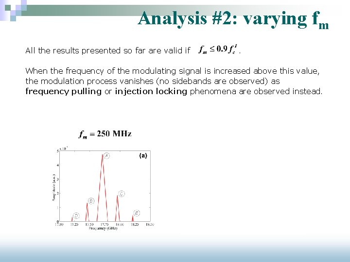
Analysis #2: varying fm All the results presented so far are valid if . When the frequency of the modulating signal is increased above this value, the modulation process vanishes (no sidebands are observed) as frequency pulling or injection locking phenomena are observed instead.
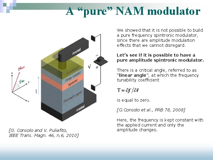
A “pure” NAM modulator We showed that it is not possible to build a pure frequency spintronic modulator, since there amplitude modulation effects that we cannot disregard. Let’s see if it is possible to have a pure amplitude spintronic modulator. There is a critical angle, referred to as “linear angle”, at which the frequency tunability coefficient is equal to zero. [G. Consolo et al. , PRB 78, 2008] [G. Consolo and V. Puliafito, IEEE Trans. Magn. 46, n. 6, 2010] Here, the frequency is kept constant with the applied current and only the amplitude changes.
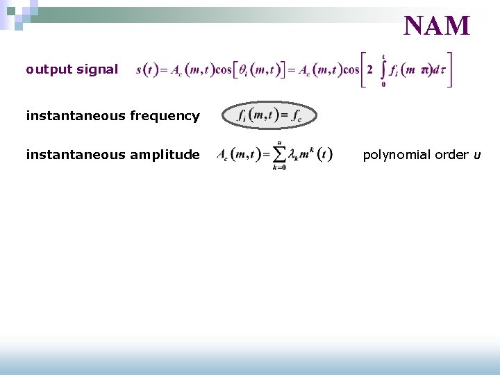
NAM output signal instantaneous frequency polynomial order u instantaneous amplitude § § central frequency = fc § number of sidebands = 2*u symmetric sidebands
Analysis #3: a pure NAM Analysis with no modulation (dc current) Analysis with modulation (dc+ac current) Numeric results agree with the analytical model: at the “linear” angle configuration, the STO works as a pure NAM!
Conclusions n We developed a general analytical model for a nonlinear combined frequency-amplitude modulation process n It has been tested on a point-contact structure: ¨ it generally works as a nonlinear modulator of both frequency and amplitude (in the range fm<0. 9 fc. I) ¨ in the “linear angle” configuration, it works as a nonlinear modulator of the sole amplitude Modulazione non lineare di ampiezza e frequenza in nano-oscillatori spintronici Vito Puliafito - ET 2010, Napoli, 11/06/2010
ww 2. unime. it/mrg/IEEE GRAZIE PER L’ATTENZIONE Modulazione non lineare di ampiezza e frequenza in nano-oscillatori spintronici Vito Puliafito - ET 2010, Napoli, 11/06/2010