Vacuum in the MDI Region Ray VENESS CERN
- Slides: 13
Vacuum in the MDI Region Ray VENESS CERN TE/VSC With thanks for useful discussions with: Konrad Elsener, Cedric Garion, Lau Gatignon, Alain Herve, Andre Sailer, Edda Gschwendtner
Introduction o CLIC MDI Vacuum o Three separate systems: CLIC detector(s), QD 0, post-collision line o o Significantly different geometry and functional requirements Linked by the same CLIC vacuum system o Physically linked by vacuum chambers o Coupled by beam dynamics and pressure distributions o Status o CLIC MDI Vacuum is still at a conceptual level, but we are not starting from zero- We can learn from: o CLIC machine (module) vacuum design o ILC design - particularly for detectors o LHC vacuum – particularly for technology o Contents of the talk o For each of the 3 systems: Detectors, QD 0, post-collision o Brief overview of what we know o Issues that need to be addressed for the CLIC CDR CLIC-MDIWG 6 XI 09 MDI beam vacuum - R. Veness
CLIC-MDIWG 6 XI 09 MDI beam vacuum - R. Veness
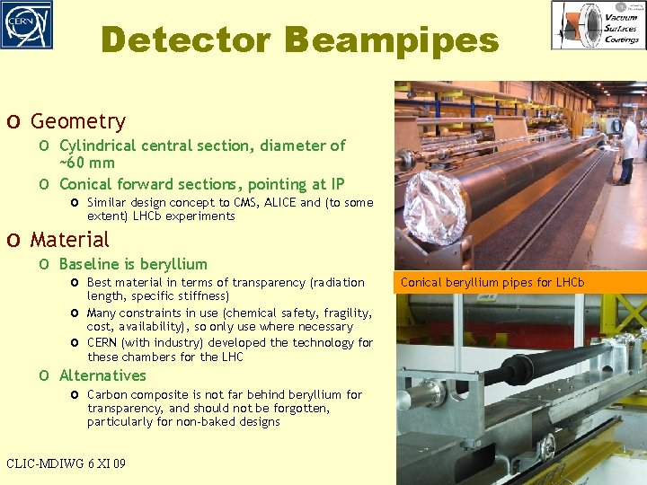
Detector Beampipes o Geometry o Cylindrical central section, diameter of o ~60 mm Conical forward sections, pointing at IP o Similar design concept to CMS, ALICE and (to some extent) LHCb experiments o Material o Baseline is beryllium o Best material in terms of transparency (radiation o o length, specific stiffness) Many constraints in use (chemical safety, fragility, cost, availability), so only use where necessary CERN (with industry) developed the technology for these chambers for the LHC Conical beryllium pipes for LHCb o Alternatives o Carbon composite is not far behind beryllium for transparency, and should not be forgotten, particularly for non-baked designs CLIC-MDIWG 6 XI 09 MDI beam vacuum - R. Veness
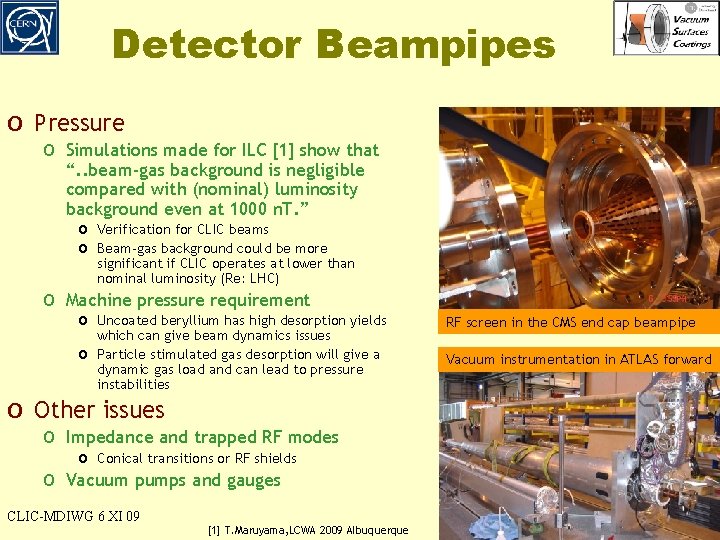
Detector Beampipes o Pressure o Simulations made for ILC [1] show that “. . beam-gas background is negligible compared with (nominal) luminosity background even at 1000 n. T. ” o Verification for CLIC beams o Beam-gas background could be more significant if CLIC operates at lower than nominal luminosity (Re: LHC) o Machine pressure requirement o Uncoated beryllium has high desorption yields RF screen in the CMS end cap beampipe o Vacuum instrumentation in ATLAS forward which can give beam dynamics issues Particle stimulated gas desorption will give a dynamic gas load and can lead to pressure instabilities o Other issues o Impedance and trapped RF modes o o Conical transitions or RF shields Vacuum pumps and gauges CLIC-MDIWG 6 XI 09 [1] T. Maruyama, LCWA 2009 Albuquerque MDI beam vacuum - R. Veness
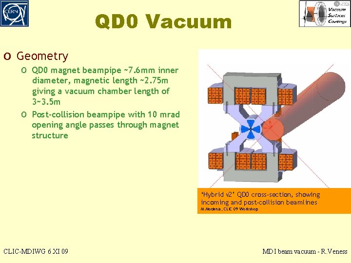
QD 0 Vacuum o Geometry o QD 0 magnet beampipe ~7. 6 mm inner o diameter, magnetic length ~2. 75 m giving a vacuum chamber length of 3~3. 5 m Post-collision beampipe with 10 mrad opening angle passes through magnet structure ‘Hybrid v 2’ QD 0 cross-section, showing incoming and post-collision beamlines M. Modena, CLIC 09 Workshop CLIC-MDIWG 6 XI 09 MDI beam vacuum - R. Veness
QD 0 Magnet Vacuum o Vacuum system o Requirements o ILC simulations suggest beam-gas is not an issue (see detector beamipes slides) o Beam dynamics requirement for CLIC is under investigation (G. Rumolo) o Design options o CLIC module concept o uses distributed pumping (NEG strips) to achieve 10 -8 mbar (10 n. T) dynamic pressure o o specification. This solution will not fit inside the QD 0 permanent magnet design o NEG-coated tube o Cylindrical chamber with ~1 µm of NEG alloy sputtered on inner wall. o Activated by heating the chamber under vacuum to 180+ºC o Activation compatible with Curie temperature of permanent magnets o Technology for sputtering inside small tubes and activation heating to be developed Unbaked tube o Simple, unbaked cylindrical chamber, pumped from extremities of magnet o Pump-down time is conductance limited and may prove excessive, depending on pressure o requirement Preliminary calculation gives ~5 x 10 CLIC-MDIWG 6 XI 09 -7 mbar (~400 n. T) after 100 hours pumping MDI beam vacuum - R. Veness
CLIC-MDIWG 6 XI 09 MDI beam vacuum - R. Veness
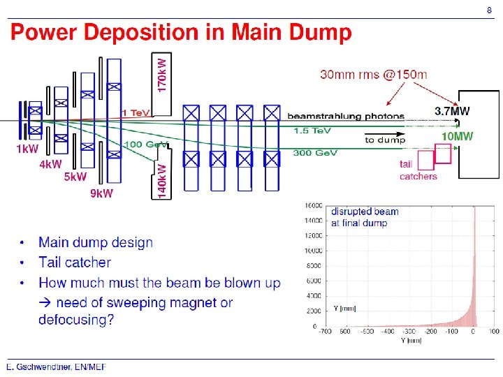
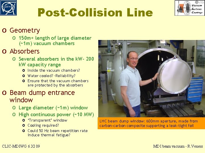
Post-Collision Line o Geometry o 150 m+ length of large diameter (~1 m) vacuum chambers o Absorbers o Several absorbers in the k. W- 200 k. W capacity range o Inside the vacuum chambers? o Water cooled? –Reliability? o Ensure that the vacuum chambers are protected by the absorbers o Beam dump entrance window o Large diameter (~1 m) window o High continuous power (~10 MW) o ‘Transparent’ window o Cooling required? o Could 50 Hz beam repetition rate LHC beam dump window: 600 mm aperture, made from carbon-carbon composite supporting a leak-tight foil induce thermal fatigue? CLIC-MDIWG 6 XI 09 MDI beam vacuum - R. Veness
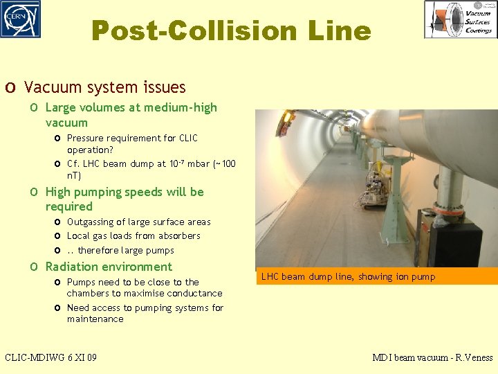
Post-Collision Line o Vacuum system issues o Large volumes at medium-high vacuum o Pressure requirement for CLIC o operation? Cf. LHC beam dump at 10 -7 mbar (~100 n. T) o High pumping speeds will be o required o Outgassing of large surface areas o Local gas loads from absorbers o. . therefore large pumps Radiation environment o Pumps need to be close to the o LHC beam dump line, showing ion pump chambers to maximise conductance Need access to pumping systems for maintenance CLIC-MDIWG 6 XI 09 MDI beam vacuum - R. Veness
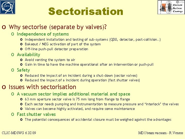
Sectorisation o Why sectorise (separate by valves)? o Independence of systems o o o Independent installation and testing of sub-systems (QD 0, detector, post-collision. . ) o Bakeout / NEG activation of part of the system o Off-line push-pull detector preparation Availability o Avoid venting the system to air o Gain in time to have the machine operational after an intervention or push-pull Safety o Reduced the impact of an incident during a shut-down (sector valves) o Reduced the impact of a incident during operation (fast shutter valves) o Issues with sectorisation o A vacuum sector implies additional material and space o o 63 mm aperture sector valve is 75 mm long from flange to flange o Each sector needs pumping and instrumentation to measure pressure and ‘interlock’ the valves o Valves can become highly activated, and require some maintenance Fast shutter valves o The potential consequences of accidental closure must be weighed against the advantages CLIC-MDIWG 6 XI 09 MDI beam vacuum - R. Veness
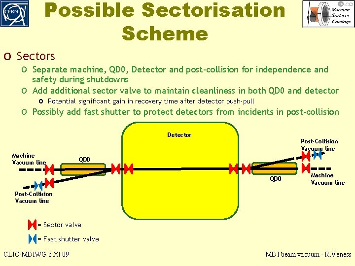
Possible Sectorisation Scheme o Sectors o Separate machine, QD 0, Detector and post-collision for independence and o o safety during shutdowns Add additional sector valve to maintain cleanliness in both QD 0 and detector o Potential significant gain in recovery time after detector push-pull Possibly add fast shutter to protect detectors from incidents in post-collision Detector Machine Vacuum line Post-Collision Vacuum line QD 0 Machine Vacuum line Post-Collision Vacuum line = Sector valve = Fast shutter valve CLIC-MDIWG 6 XI 09 MDI beam vacuum - R. Veness
Summary o Pressure requirements o Dynamic (ie, with beam) pressure requirements need to be o o specified o For QD 0, detector and post-collision regions o Sum of requirements from both detectors and machine Some information exists for ILC o This needs to be verified for CLIC This is an urgent pre-requisite for the QD 0 vacuum system design o Sectorisation o Complete design not essential now, but space in critical areas (eg, o between detector and QD 0? ) should be reserved Linked to questions of bakeout of components and re-start time after push-pull CLIC-MDIWG 6 XI 09 MDI beam vacuum - R. Veness