MDI Vacuum Status Ray VENESS CERN TEVSC Introduction
- Slides: 9
MDI Vacuum Status Ray VENESS CERN TE-VSC
Introduction o Pressure requirements for QD 0 and the experimental o o sector Pressure profile for QD 0 Vacuum layout in the MDI Post-collision line Conclusions and open questions FP 420 13 X 08 Warm beampipe - R. Veness
Pressure Requirements for QD 0 and Experiment o Requirements from beam dynamics o Recent calculations from Rumolo [1] show that coherent instabilities are o not an issue if pressures with pressures in the last 20 m of the BDS upto 105 n. Torr (~1. 3 x 10 -4 mbar) He notes however that incoherent effects and emittance growth should be studied o Requirements from the experiments o ILC simulations [2] suggest that beam-gas background is not an issue at o 103 n. Torr (~1. 3 x 10 -6 mbar) This needs to be confirmed for the CLIC experiments o These pressure requirements suggest that a non-baked solution could be adopted for the QD 0, and possibly also the experimental sector CLIC-MDIWG 6 XI 09 [1] G. Rumolo, CLIC-MDI meeting March 2010 [2] T. Maruyama, LCWA 2009 Albuquerque MDI beam vacuum - R. Veness
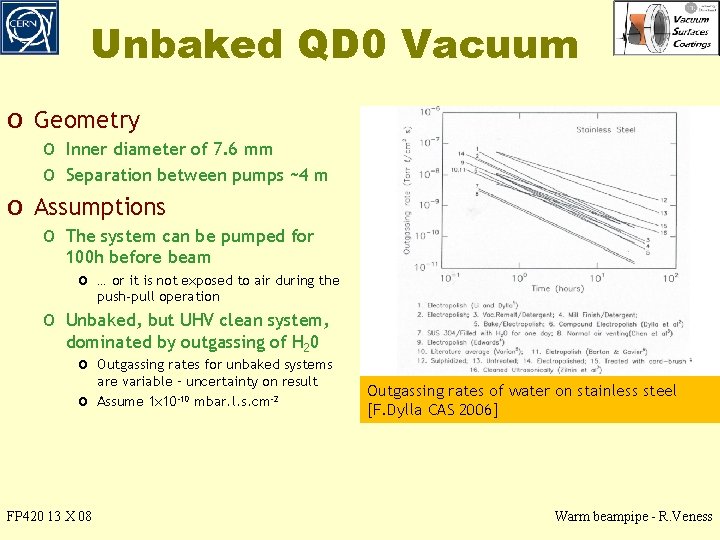
Unbaked QD 0 Vacuum o Geometry o Inner diameter of 7. 6 mm o Separation between pumps ~4 m o Assumptions o The system can be pumped for 100 h before beam o … or it is not exposed to air during the push-pull operation o Unbaked, but UHV clean system, dominated by outgassing of H 20 o Outgassing rates for unbaked systems o FP 420 13 X 08 are variable – uncertainty on result Assume 1 x 10 -10 mbar. l. s. cm-2 Outgassing rates of water on stainless steel [F. Dylla CAS 2006] Warm beampipe - R. Veness
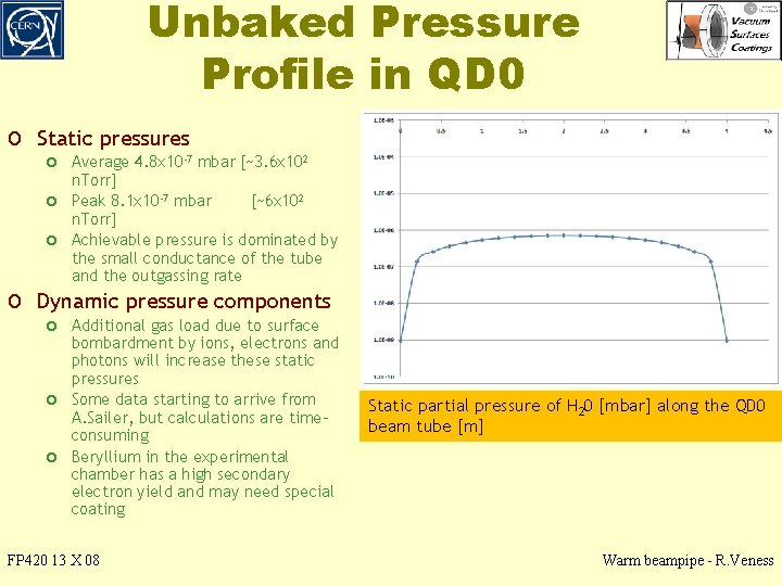
Unbaked Pressure Profile in QD 0 o Static pressures o Average 4. 8 x 10 -7 mbar [~3. 6 x 10² o o n. Torr] Peak 8. 1 x 10 -7 mbar [~6 x 10² n. Torr] Achievable pressure is dominated by the small conductance of the tube and the outgassing rate o Dynamic pressure components o Additional gas load due to surface o o bombardment by ions, electrons and photons will increase these static pressures Some data starting to arrive from A. Sailer, but calculations are timeconsuming Beryllium in the experimental chamber has a high secondary electron yield and may need special coating FP 420 13 X 08 Static partial pressure of H 20 [mbar] along the QD 0 beam tube [m] Warm beampipe - R. Veness
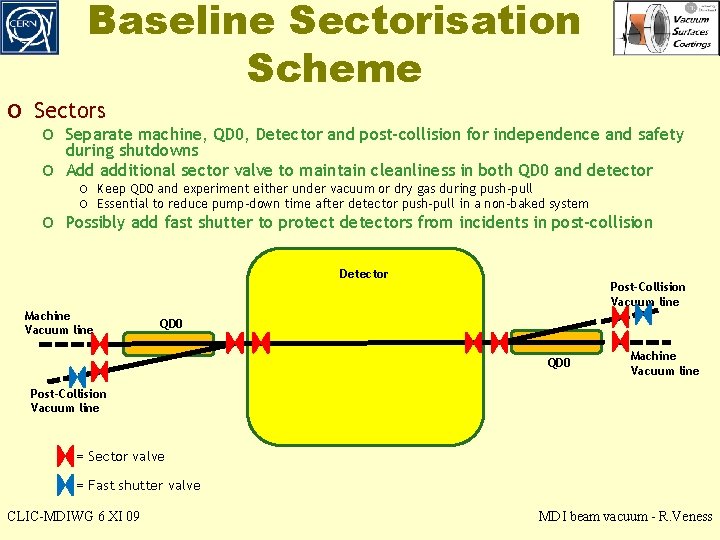
Baseline Sectorisation Scheme o Sectors o Separate machine, QD 0, Detector and post-collision for independence and safety o during shutdowns Add additional sector valve to maintain cleanliness in both QD 0 and detector o Keep QD 0 and experiment either under vacuum or dry gas during push-pull o Essential to reduce pump-down time after detector push-pull in a non-baked system o Possibly add fast shutter to protect detectors from incidents in post-collision Detector Machine Vacuum line Post-Collision Vacuum line QD 0 Machine Vacuum line Post-Collision Vacuum line = Sector valve = Fast shutter valve CLIC-MDIWG 6 XI 09 MDI beam vacuum - R. Veness
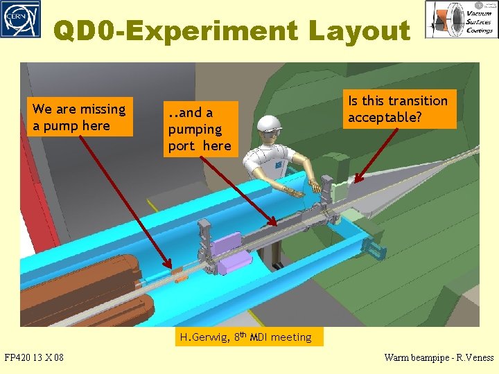
QD 0 -Experiment Layout We are missing a pump here . . and a pumping port here Is this transition acceptable? H. Gerwig, 8 th MDI meeting FP 420 13 X 08 Warm beampipe - R. Veness
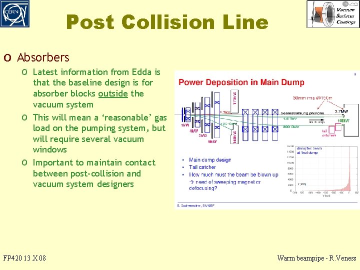
Post Collision Line o Absorbers o Latest information from Edda is o o that the baseline design is for absorber blocks outside the vacuum system This will mean a ‘reasonable’ gas load on the pumping system, but will require several vacuum windows Important to maintain contact between post-collision and vacuum system designers FP 420 13 X 08 Warm beampipe - R. Veness
Conclusions and Open Issues o Unbaked QD 0 design presented o Average static pressure 4. 8 x 10 -7 mbar [~3. 6 x 10² n. Torr] o This will need 2 sector valves between QD 0 and experiment for rapid o recovery after push-pull and pumps on both ends of QD 0 Pumping on both ends of QD 0 is essential, as well as a port for pumping the space between the 2 valves o Open issues for pressure profiles o Ion, electron and photon induced desorption rates need to be calculated o Other beam dynamics requirements? o Incoherent effects and emittance growth o Wall impedance requirement for vacuum chambers o low resistivity coatings? o Beampipe geometry transitions? o Trapped RF modes giving coherent/incoherent losses and heating effects o Next steps o Confirm the acceptability of unbaked design in QD 0 o Calculate static pressure profile in an unbaked experimental sector FP 420 13 X 08 Warm beampipe - R. Veness