
Gas Jet Simulations Paolo Magagnin and Ray Veness





- Slides: 29
Gas Jet Simulations Paolo Magagnin and Ray Veness 11/10/2016 Paolo Magagnin/Ray Veness 1
Contents • Background and Objectives • Simulation Issues and strategy • Simulations: • • Benchmarking Flow into a high pressure chamber Flow into the ‘Cockcroft Prototype’ pressure chamber Addition of Skimmer 1 • Summary and next steps 11/10/2016 Paolo Magagnin/Ray Veness 2
Background and Objectives • Considerable simulation work has been done for gas jet dynamics, most recently at Cockcroft* • Two main reasons for continuing this work: • Need a design tool for optimising this instrument • Optimal spacing, diameter and geometry of nozzle skimmers • Pressure and hence pumping requirements from the vacuum system • Input for alignment precision of skimmers • Previous studies have focussed on the ‘high pressure’ end of the system • Tools and expertise are available at CERN to analyse the low pressure (molecular flow) regime • Could provide input for pumping system design, gas jet shaper and beam-gas interaction region *M. Putignano, C. P. Welsch, Nuc. Inst. Methods A, 667 (2012) 44 -52 11/10/2016 Paolo Magagnin/Ray Veness 3
Simulation issues • Pressure range spans 11 orders of magnitude • Gas nozzle inlet at 10 Bar, Interaction chamber at ~10 -7 mbar • Transition from viscous to molecular flow regimes mean the same physical models cannot be used over the whole flow • Geometric details also range over 4 to 5 orders of magnitude • Nozzles from ~30 µm with transport over ~ 1 m • Tends to require numerical models with large numbers of elements, so computationally demanding 11/10/2016 Paolo Magagnin/Ray Veness 4
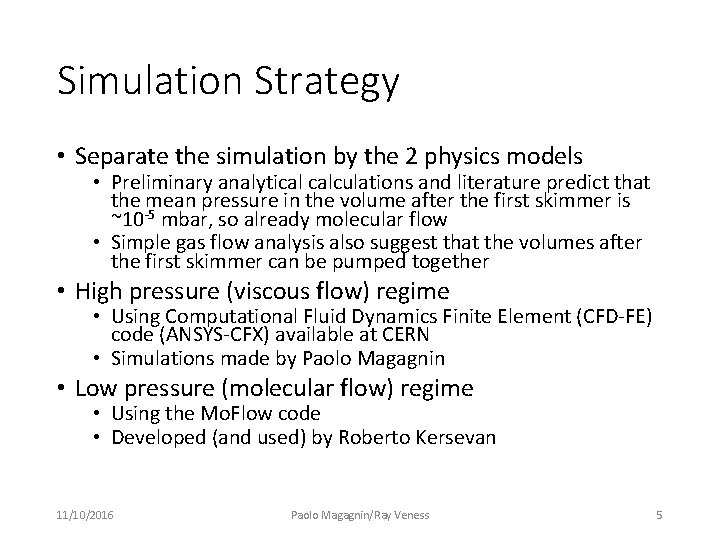
Simulation Strategy • Separate the simulation by the 2 physics models • Preliminary analytical calculations and literature predict that the mean pressure in the volume after the first skimmer is ~10 -5 mbar, so already molecular flow • Simple gas flow analysis also suggest that the volumes after the first skimmer can be pumped together • High pressure (viscous flow) regime • Using Computational Fluid Dynamics Finite Element (CFD-FE) code (ANSYS-CFX) available at CERN • Simulations made by Paolo Magagnin • Low pressure (molecular flow) regime • Using the Mo. Flow code • Developed (and used) by Roberto Kersevan 11/10/2016 Paolo Magagnin/Ray Veness 5
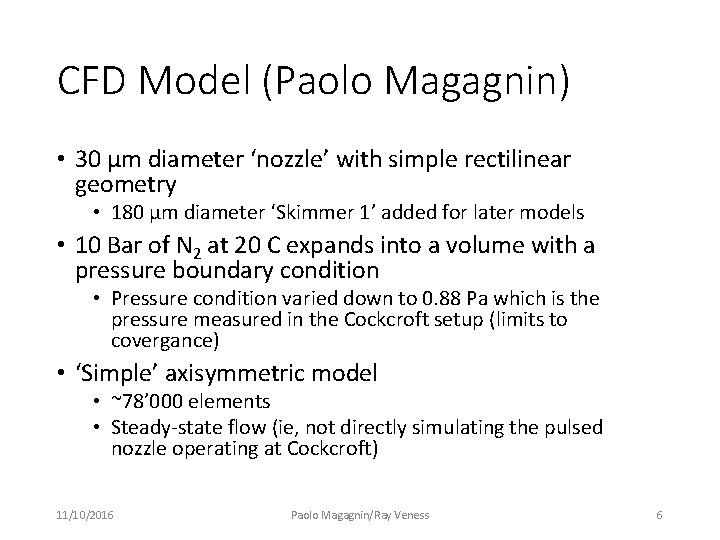
CFD Model (Paolo Magagnin) • 30 µm diameter ‘nozzle’ with simple rectilinear geometry • 180 µm diameter ‘Skimmer 1’ added for later models • 10 Bar of N 2 at 20 C expands into a volume with a pressure boundary condition • Pressure condition varied down to 0. 88 Pa which is the pressure measured in the Cockcroft setup (limits to covergance) • ‘Simple’ axisymmetric model • ~78’ 000 elements • Steady-state flow (ie, not directly simulating the pulsed nozzle operating at Cockcroft) 11/10/2016 Paolo Magagnin/Ray Veness 6
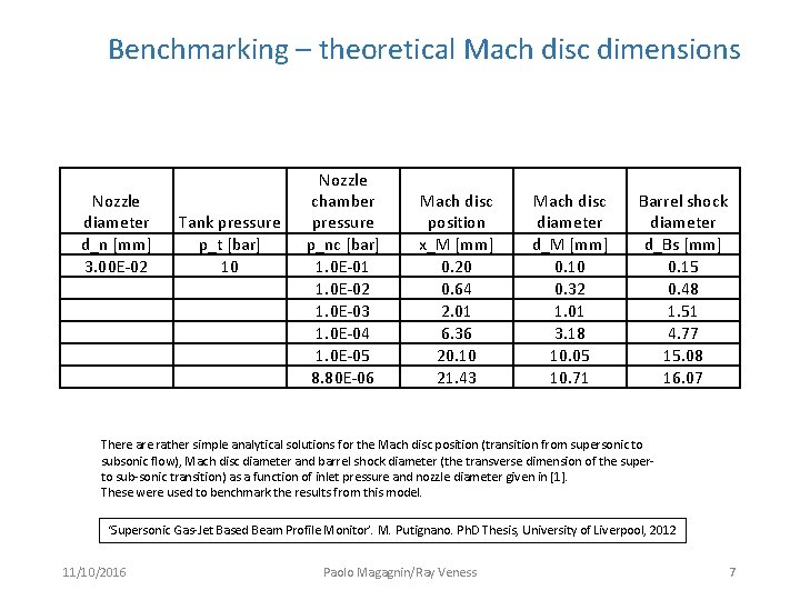
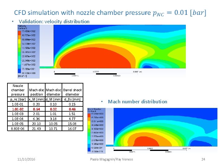
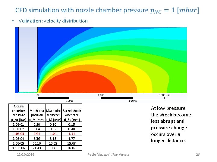
Benchmarking – theoretical Mach disc dimensions Nozzle diameter d_n [mm] 3. 00 E-02 Tank pressure p_t [bar] 10 Nozzle chamber pressure p_nc [bar] 1. 0 E-01 1. 0 E-02 1. 0 E-03 1. 0 E-04 1. 0 E-05 8. 80 E-06 Mach disc position x_M [mm] 0. 20 0. 64 2. 01 6. 36 20. 10 21. 43 Mach disc diameter d_M [mm] 0. 10 0. 32 1. 01 3. 18 10. 05 10. 71 Barrel shock diameter d_Bs [mm] 0. 15 0. 48 1. 51 4. 77 15. 08 16. 07 There are rather simple analytical solutions for the Mach disc position (transition from supersonic to subsonic flow), Mach disc diameter and barrel shock diameter (the transverse dimension of the super- to sub-sonic transition) as a function of inlet pressure and nozzle diameter given in [1]. These were used to benchmark the results from this model. ‘Supersonic Gas-Jet Based Beam Profile Monitor’. M. Putignano. Ph. D Thesis, University of Liverpool, 2012 11/10/2016 Paolo Magagnin/Ray Veness 7
• Velocity distribution 11/10/2016 Paolo Magagnin/Ray Veness 8
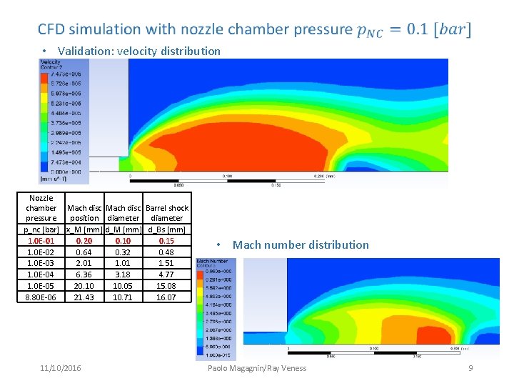
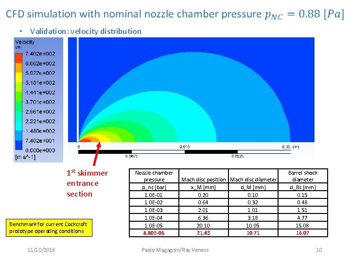
• Validation: velocity distribution Nozzle chamber Mach disc Barrel shock pressure position diameter p_nc [bar] x_M [mm] d_Bs [mm] 1. 0 E-01 0. 20 0. 15 1. 0 E-02 0. 64 0. 32 0. 48 1. 0 E-03 2. 01 1. 51 1. 0 E-04 6. 36 3. 18 4. 77 1. 0 E-05 20. 10 10. 05 15. 08 8. 80 E-06 21. 43 10. 71 16. 07 11/10/2016 • Mach number distribution Paolo Magagnin/Ray Veness 9
• Validation: velocity distribution 1 st skimmer entrance section Benchmark for current Cockcroft prototype operating conditions 11/10/2016 Nozzle chamber pressure p_nc [bar] 1. 0 E-01 1. 0 E-02 1. 0 E-03 1. 0 E-04 1. 0 E-05 8. 80 E-06 Mach disc position Mach disc diameter x_M [mm] d_M [mm] 0. 20 0. 10 0. 64 0. 32 2. 01 1. 01 6. 36 3. 18 20. 10 10. 05 21. 43 10. 71 Paolo Magagnin/Ray Veness Barrel shock diameter d_Bs [mm] 0. 15 0. 48 1. 51 4. 77 15. 08 16. 07 10
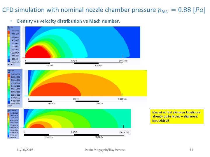
• Density vs velocity distribution vs Mach number. Gas jet at first skimmer location is already quite broad – alignment less critical? 11/10/2016 Paolo Magagnin/Ray Veness 11
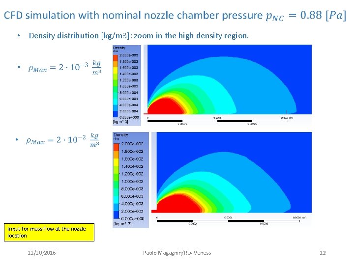
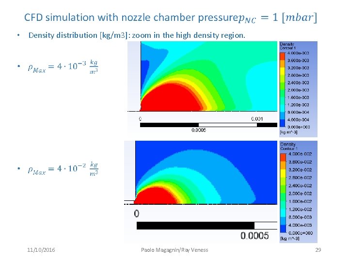
• Density distribution [kg/m 3]: zoom in the high density region. Input for mass flow at the nozzle location 11/10/2016 Paolo Magagnin/Ray Veness 12
• Flow direction 11/10/2016 Paolo Magagnin/Ray Veness 13
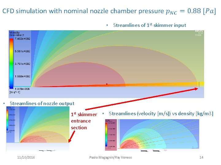
• Streamlines of 1 st skimmer input • Streamlines of nozzle output 1 st skimmer • Streamlines (velocity [m/s]) vs density [kg/m 3] entrance section 11/10/2016 Paolo Magagnin/Ray Veness 14
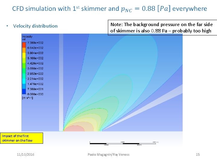
• Velocity distribution Note: The background pressure on the far side of skimmer is also 0. 88 Pa – probably too high Impact of the first skimmer on the flow 11/10/2016 Paolo Magagnin/Ray Veness 15
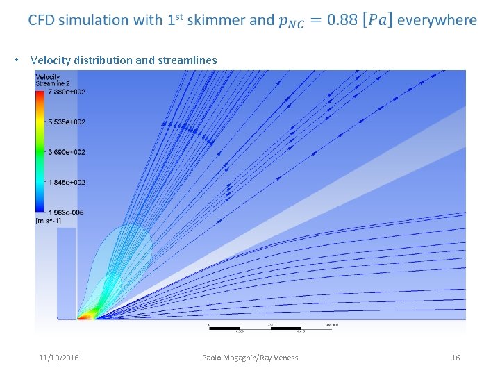
• Velocity distribution and streamlines 11/10/2016 Paolo Magagnin/Ray Veness 16
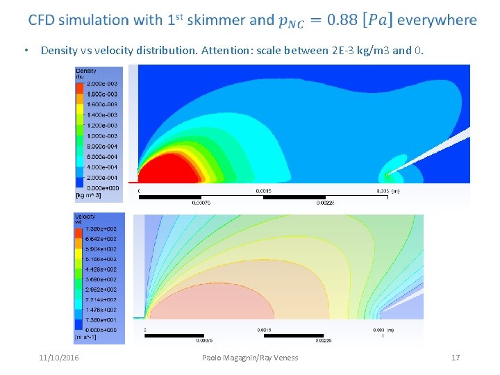
• Density vs velocity distribution. Attention: scale between 2 E-3 kg/m 3 and 0. 11/10/2016 Paolo Magagnin/Ray Veness 17
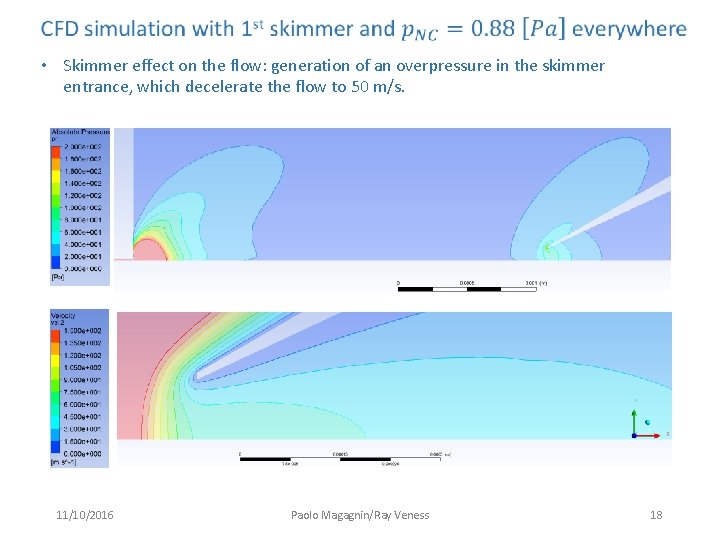
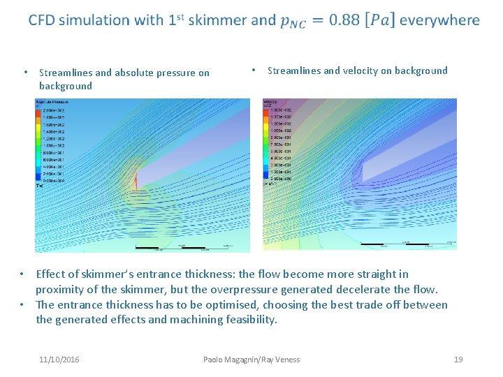
• Skimmer effect on the flow: generation of an overpressure in the skimmer entrance, which decelerate the flow to 50 m/s. 11/10/2016 Paolo Magagnin/Ray Veness 18
• Streamlines and absolute pressure on background • Streamlines and velocity on background • Effect of skimmer’s entrance thickness: the flow become more straight in proximity of the skimmer, but the overpressure generated decelerate the flow. • The entrance thickness has to be optimised, choosing the best trade off between the generated effects and machining feasibility. 11/10/2016 Paolo Magagnin/Ray Veness 19
What have we achieved so far? • Produced a CFD model that benchmarks well with analytical solutions from Putignano’s thesis • Produced a data set that can be used as input for the Mo. Flow calculation • Simulations with different pressure in the nozzle chamber • confirm that lower pressures extend the length of the supersonic region, where the first skimmer should be located • The model shows that alignment in offset/angle of the first skimmer should not be critical in the range of ~ diameters • First to second skimmer alignment may be more critical • Insertion of the first skimmer has a significant impact on the gas flow • Gas flow lines are re-directed, but velocity appears significantly retarded 11/10/2016 Paolo Magagnin/Ray Veness 20
Possible issues and improvements • Possible improvements to the model: • The Cockcroft prototype is operated in a ‘pulsed’ mode. Does the pressure in the nozzle have time to fully develop? Can this be modelled? • A 3 D model would allow the pumping environment and skimmer alignment to be modelled. Is this justified? • Possible improvements to the design: • Benefits from reducing the gas temperature to increase density? This is a solution used in gas jet targets • Details of the nozzle – would a micro ‘de Laval’ or other nozzle geometry help? This is a current research field for satellite propulsion systems • Details of the first skimmer are important – significant impact on gas velocity and direction • CERN are now missing personnel to do this work… 11/10/2016 Paolo Magagnin/Ray Veness 21
Additional Material 11/10/2016 Paolo Magagnin/Ray Veness 22
• Velocity distribution 11/10/2016 Paolo Magagnin/Ray Veness 23
• Validation: velocity distribution Nozzle chamber Mach disc Barrel shock pressure position diameter p_nc [bar] x_M [mm] d_Bs [mm] 1. 0 E-01 0. 20 0. 15 1. 0 E-02 0. 64 0. 32 0. 48 1. 0 E-03 2. 01 1. 51 1. 0 E-04 6. 36 3. 18 4. 77 1. 0 E-05 20. 10 10. 05 15. 08 8. 80 E-06 21. 43 10. 71 16. 07 11/10/2016 • Mach number distribution Paolo Magagnin/Ray Veness 24
• Velocity distribution 11/10/2016 Paolo Magagnin/Ray Veness 25
• Validation: velocity distribution Nozzle chamber Mach disc Barrel shock pressure position diameter p_nc [bar] x_M [mm] d_Bs [mm] 1. 0 E-01 0. 20 0. 15 1. 0 E-02 0. 64 0. 32 0. 48 1. 0 E-03 2. 01 1. 51 1. 0 E-04 6. 36 3. 18 4. 77 1. 0 E-05 20. 10 10. 05 15. 08 8. 80 E-06 21. 43 10. 71 16. 07 11/10/2016 At low pressure the shock become less abrupt and pressure change occurs over a longer distance. Paolo Magagnin/Ray Veness 26
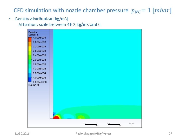
• Density distribution [kg/m 3] Attention: scale between 4 E-3 kg/m 3 and 0. 11/10/2016 Paolo Magagnin/Ray Veness 27
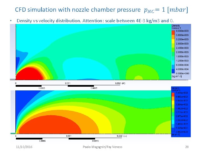
• Density vs velocity distribution. Attention: scale between 4 E-3 kg/m 3 and 0. 11/10/2016 Paolo Magagnin/Ray Veness 28
• Density distribution [kg/m 3]: zoom in the high density region. 11/10/2016 Paolo Magagnin/Ray Veness 29