UNIX Block Diagram of the System Kernel User

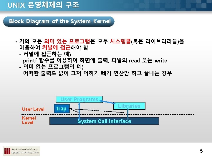
UNIX 운영체제의 구조 Block Diagram of the System Kernel User Programs Libraries trap User Level Kernel Level System Call Interface File Subsystem Buffer cache Character Block Process Inter-process communication Control Scheduler Subsystem Device drivers Memory management hardware control hardware Hardware Level 4
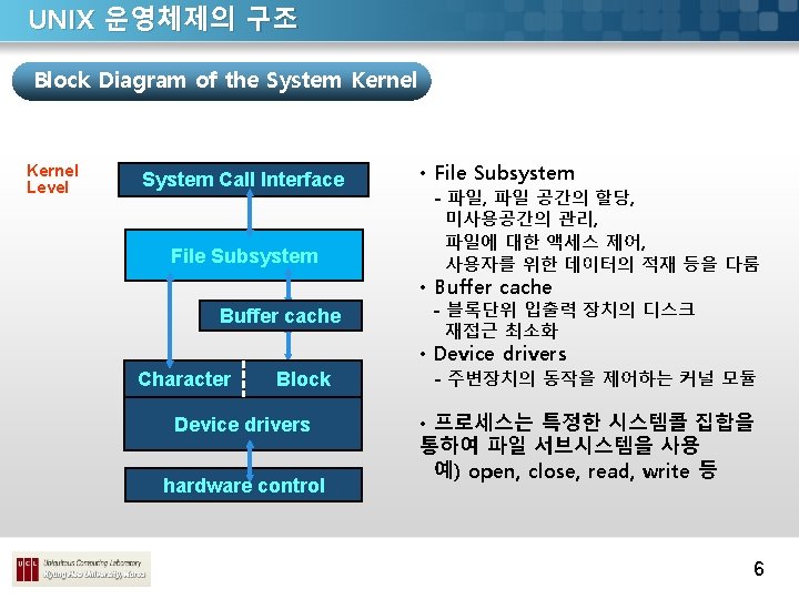

UNIX 운영체제의 구조 Block Diagram of the System Kernel Level System Call Interface Process Control Subsystem Inter-process communication Scheduler Memory management hardware control • Process Control Subsystem • IPC - 프로세스간 통신 • Scheduler - 프로세스에게 CPU 할당 • Memory management - 메모리의 할당을 제어 - 스와핑과 요구 페이징 전략을 사용 이를 통해 메모리 부족을 극복 • Hardware control - 인터럽트 처리 및 컴퓨터와의 통신 역할 7

UNIX 운영체제의 구조 Block Diagram of the System Kernel Level File Subsystem Process Inter-process communication Control Scheduler Subsystem Memory management • Process Control Subsystem은 파일을 실행 전 해당 파일을 먼저 메모리 로 읽어 들여야 하는데, 이 때 두 Subsystem은 상호작용을 하게 됨 8

UNIX 운영체제의 구조 Block Diagram of the System Kernel User Programs Libraries trap User Level Kernel Level System Call Interface File Subsystem Buffer cache Character Block Process Inter-process communication Control Scheduler Subsystem Device drivers Memory management hardware control hardware Hardware Level 9

시스템 개념의 소개 File Sub System User file descriptor table file table Inode table 11
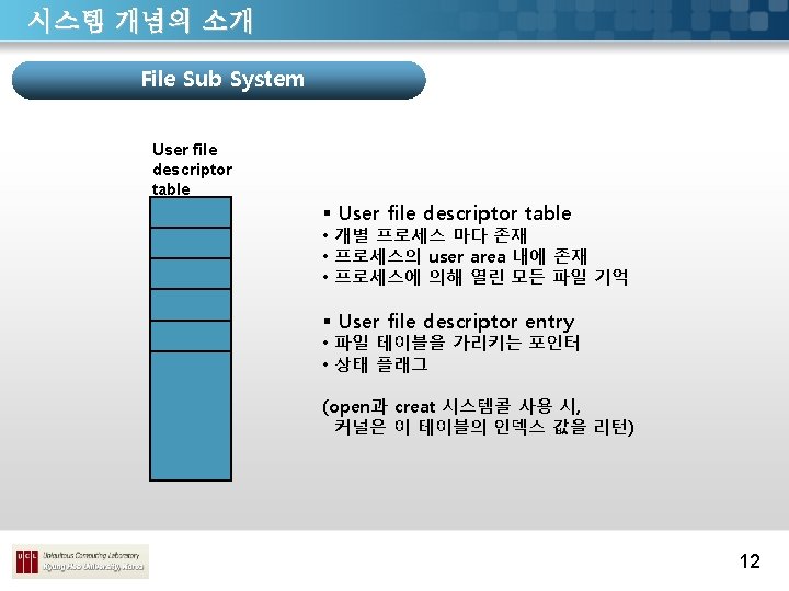
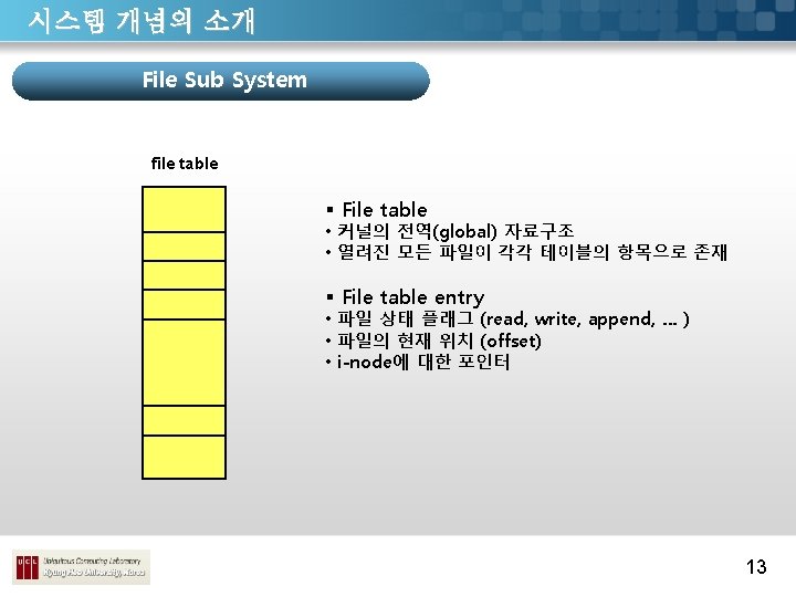
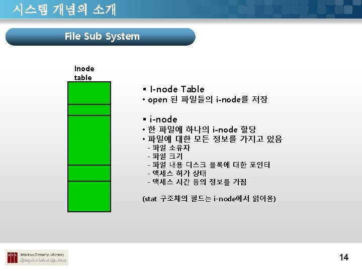

시스템 개념의 소개 File Sub System User file descriptor table file table Inode table • 동작 예) open 호출 시, 1. User file descriptor table 에 엔트 리를 할당 2. File table을 체크하고 필요하다면 엔트리를 할당 3. i-node table을 체크하고 필요하다 면 엔트리를 할당 4. User file descriptor table에 있는 엔트리의 인덱스를 반환 read 호출 시, 1. file descriptor를 사용하여 User file descriptor table을 액세스 2. File table과 i-node table 앤트리 에 대한 포인터를 따라서 해당 i-node 로부터 파일에 있는 데이터를 검색 15

시스템 개념의 소개 프로세스들의 데이터 구조 Region table Active process u area Per-process region table Process table 주 메모리 24

- Slides: 35