UNIT 4 PROGRAMMING LOGIC CONTROLLERS 12 Programmable Logic

UNIT 4: PROGRAMMING LOGIC CONTROLLERS 12 Programmable Logic Controllers – Basic Structure – Input / Output Processing – Programming – Mnemonics – Timers, Internal relays and counters – Shift Registers – Master and Jump Controls – Data Handling – Analogs Input / Output – Selection of a PLC
 • Program is")
Programmable Logic Controllers Definition of PLC: • Programmable logic controller (PLC) • Program is a specially designed digital operating microprocessor-based controller that uses a programmable memory for internal storage of instructing and for implementing function such as logic, sequencing, timing, counting and arithmetic in order to control machines and processes.

BASIC COMPONENTS: • Processor • Memory • Power Supply • Input I Output modules • Programming device • Monitor

BASIC STRUCTURE OF A PLC SYSTEM

INPUT / OUTPUT PROCESSING The sourcing and sinking are used to describe the way in which DC devices are connected to PLC Sourcing: • If a switch is connected to the positive of the battery and current flows from positive to negative, it is said to be the sourcing the current. So, the input device receives current from the input module.

Sinking: • If a switch is connected to the negative of the battery and current flows from positive to negative, by conventional current flow direction, it is said to be the sinking for Current. For the PLC output unit, the current flows from output device to the output module

STEPS INVOLVED IN INPUT / OUTPUT PROCESSING

Mnemonics

AND Logic Function: OR Logic Function:

NOT Logic Function: NAND Logic Function:
 Logic Function:")
NOR Logic Function: Exclusive OR (XOR) Logic Function:

Latching It is the instructions that use momentary switches and program the PLC so that when we push one the output turns on and when we push another the output turns off. This would be the function of a latching instruction

TIMER It is a special counter ladder function that allows the PLC to perform timing operations based on a precise internal clock. Delay ON Timers: TON is used to denote ON-delay.

Delay OFF Timers: TOF is used to denote OFFdelay. Pulse Timers:

Cascaded Timers: Timers are linked together to give longer delay times which is easily achieved than just one timer. ON – OFF Cycle Timer: Timers producing an output for some period and no output for some period an output for some period.

One Shot Timers: One shot timers produces an output for a fixed length of some initiation input.

Internal relay • A relay is an electromagnetic switch operated by a relatively small electric current that can turn on or off a much larger electric current. The heart of a relay is an electromagnet • It can be very useful in the implementation of switching sequences. • It can be used when there are programs with multiple input conditions.

Counters • It is used to count a specified number of contact operations.

Shift Register: A shift register is an electronic storage device that allows the stored bits of one relay to get shifted into another relay.

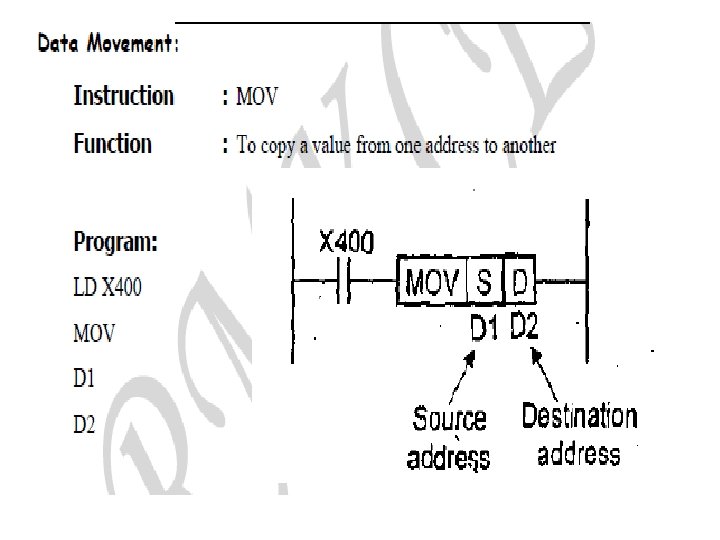
Data handling: • The steps involved in data handling with a PLC system are • Moving data from one memory location to another • Comparison of Magnitudes of data • Arithmetic operations • Data conversion
 to the input value")
Data Comparison: It compare a pre – set value (1) to the input value (2) Instruction : < or LES = or EQU > or GRT < or LEQ ≠ or <> or NEQ > or GEQ

Data Arithmetic Operations: • It is the ability to carry out the arithmetic operations such as addition, subtraction, multiplication and division only. • They cannot carry out exponential functions.

Code Conversions: • All the internal operations in the CPU of a PLC are carried out through binary numbers. • When a decimal (input) signal is given, BCD conversion is used. • Similarly, when a decimal output is required, Decimal conversion is used.
- Slides: 25