Programmable Logic Controllers Manisha Goel Lecturer EE Deptt

Programmable Logic Controllers Manisha Goel, Lecturer, EE Deptt Govt. Polytechnic Manesar

PLC’s Are. . . • Similar to a Microcontroller: – Microprocessor Based – Onboard Memory for Storing Programs – Special Programming Language: Ladder Logic – Input/Output Ports

PLC’s Are. . . • Dissimilar to Microcontrollers: – Intended for Industrial Applications – I/O Designed to interface with Control Relays – Emphasis on Maximum Reliability

PLC’s • Widely Applied in Every Industry • Were Developed to Simplify the Implementation of Control Automation Systems in Plants and Assembly Lines • Designed to Minimize the Number of Control Relays in a Process and Maximize the Ways Relays can be Used • First Applied to Automobile Industry in the Late 1960’s • Flexible, Reliable and Low Cost

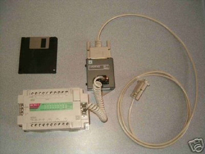
PLC Components

I/O Modules • Input Modules: Input Signals can be AC or DC, Analog or Digital • Output Modules: Outputs are either AC or DC Analog Signals (Although it is possible to ‘Construct’ Digital Outputs) • Modern PLC’s have Expansion Ports to Increase the Number of Available Inputs and Outputs
 –")
Examples of I/O Signals • Inputs: – Pushbutton (Energizing or Grounding an Input) – Relay Contact Output – DC Voltage Level – Digital Logic Signal (+5 V or 0 V, etc) • Outputs: – 24 V ac – 120 Vdc – etcetera

PLC’s Use Ladder Logic • Ladder Logic Diagrams Provide a Method to Symbolically Show How Relay Control Schemes are Implemented • Relay Contacts and Coils, Inputs and Outputs lie on “Rungs” Between the Positive and Ground Rails

Example of Ladder Diagram

Relays • In General, Relays Transform a Control Signal into a Control Action • Relays Provide: – Isolation Between Input and Output – Leverage (Small Signal Can Control Large Action) – Automation (Minimize Human Interaction with a Control Process)

Relay Components

Basic Relay Symbols

Relay Applications • Relays can be Designed to Perform Many Functions – Detect Out of Limit Conditions on Voltages and Currents – Start Motors – Prevent Motors from Over Heating – Control Assembly Lines – Adjust Lighting

PLC Special Features • • • Time Delay Relays Counter Relays Special Functions User Defined Functions Special Bits

Time Delay Relays • When TD Relay Pick-Up Coil is Energized, a Delay is Initiated • Normally Open Contacts Wait to Close until Delay is Completed • Normally Closed Contacts Wait to Open until Delay is Completed • Very Useful for Creating a Sequence of Control Events

Time Delay Symbol • Can be Constructed With or Without a Reset Input

Making Use of Delays • Delay Motor Start While Alarm Sounds for Safety

Counters • Counter Relays must “Count” a predetermined number of events before changing contact status • Can Count Up (Up. Counter) or Count Down (Down. Counter) • e. g. An Up. Counter is set to 8 and is programmed to detect every occurrence of a 5 Volt pulse. When it has detected 8 such occurrences, the NO Contacts close and the NC contacts open. • Great for making Real-Time Clocks, etc

Special Functions • Modern PLCs can perform many Math and Logic Functions without additional Ladder Logic Programming – Differentiation, Integration – +, -, *, / – Boolean Logic Functions (AND, NOT, OR) – Master Control Functions (Reset, etc)
- Slides: 20