The Advanced LIGO Angular Control System ASC Hanford

- Slides: 27
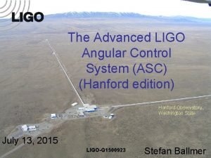
The Advanced LIGO Angular Control System (ASC) (Hanford edition) Hanford Observatory, Washington State July 13, 2015 LIGO-G 1500923 Stefan Ballmer
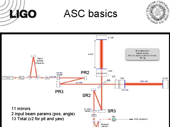
ASC basics PR 2 PR 3 11 mirrors 2 input beam params (pos, angle) 13 Total (x 2 for pit and yaw) SR 2 SR 3
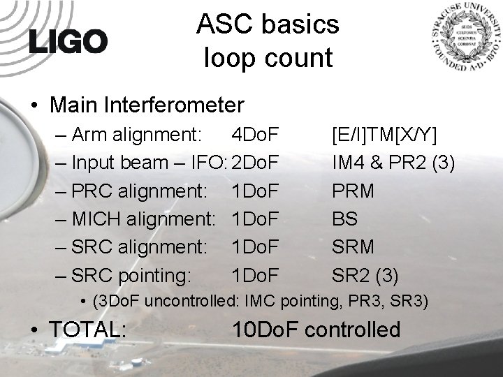
ASC basics loop count • Main Interferometer – Arm alignment: 4 Do. F – Input beam – IFO: 2 Do. F – PRC alignment: 1 Do. F – MICH alignment: 1 Do. F – SRC pointing: 1 Do. F [E/I]TM[X/Y] IM 4 & PR 2 (3) PRM BS SRM SR 2 (3) • (3 Do. F uncontrolled: IMC pointing, PR 3, SR 3) • TOTAL: 10 Do. F controlled
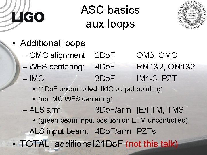
ASC basics aux loops • Additional loops – OMC alignment – WFS centering: – IMC: 2 Do. F 4 Do. F 3 Do. F OM 3, OMC RM 1&2, OM 1&2 IM 1 -3, PZT • (1 Do. F uncontrolled: IMC output pointing) • (no IMC WFS centering) – ALS arm: 3 Do. F/arm [E/I]TM, TMS • (green beam input position on ETM uncontrolled) – ALS input beam: 4 Do. F/arm PZTs • TOTAL: additional 21 Do. F (not this talk)
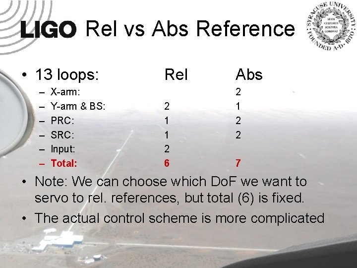
Rel vs Abs Reference • 13 loops: – – – X-arm: Y-arm & BS: PRC: SRC: Input: Total: Rel 2 1 1 2 6 Abs 2 1 2 2 7 • Note: We can choose which Do. F we want to servo to rel. references, but total (6) is fixed. • The actual control scheme is more complicated
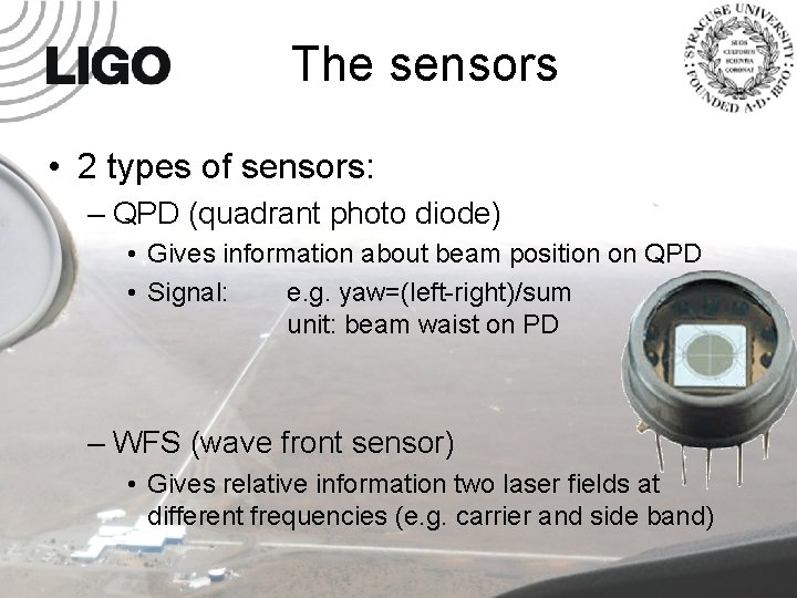
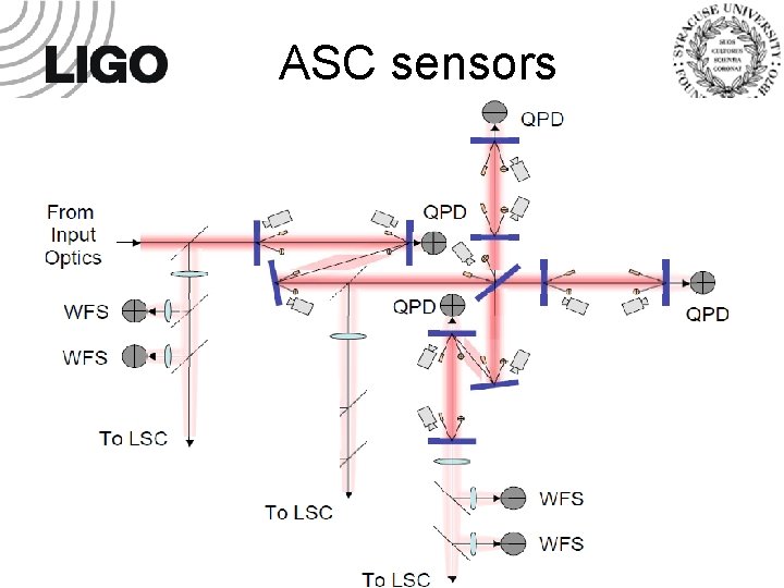
The sensors • 2 types of sensors: – QPD (quadrant photo diode) • Gives information about beam position on QPD • Signal: e. g. yaw=(left-right)/sum unit: beam waist on PD – WFS (wave front sensor) • Gives relative information two laser fields at different frequencies (e. g. carrier and side band)
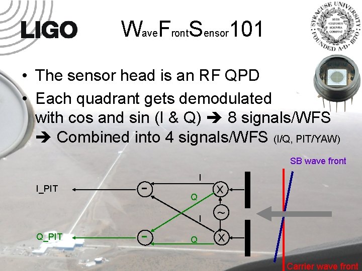
Wave. Front. Sensor 101 • The sensor head is an RF QPD • Each quadrant gets demodulated with cos and sin (I & Q) 8 signals/WFS Combined into 4 signals/WFS (I/Q, PIT/YAW) SB wave front I_PIT - I Q_PIT - Q x ~ x Carrier wave front
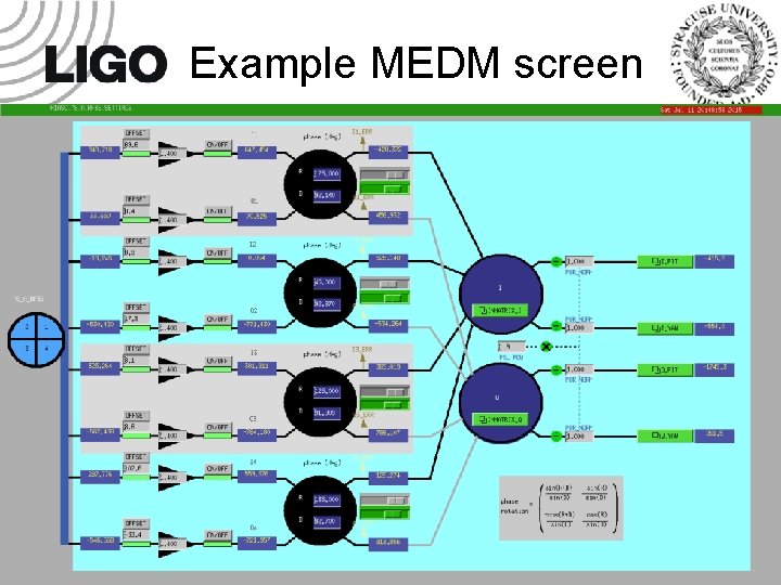
Example MEDM screen
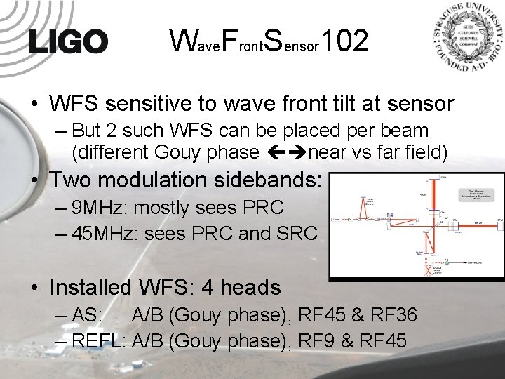
Wave. Front. Sensor 102 • WFS sensitive to wave front tilt at sensor – But 2 such WFS can be placed per beam (different Gouy phase near vs far field) • Two modulation sidebands: – 9 MHz: mostly sees PRC – 45 MHz: sees PRC and SRC • Installed WFS: 4 heads – AS: A/B (Gouy phase), RF 45 & RF 36 – REFL: A/B (Gouy phase), RF 9 & RF 45
ASC sensors
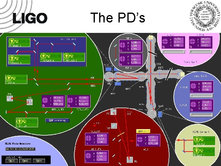
The PD’s
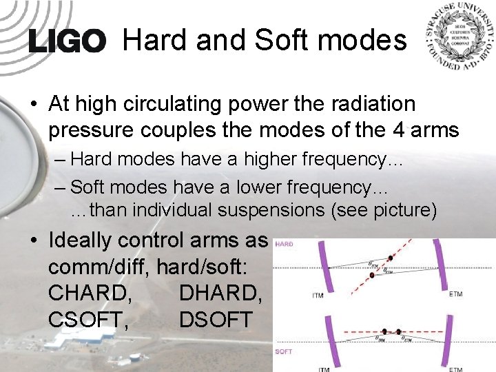
Hard and Soft modes • At high circulating power the radiation pressure couples the modes of the 4 arms – Hard modes have a higher frequency… – Soft modes have a lower frequency… …than individual suspensions (see picture) • Ideally control arms as comm/diff, hard/soft: CHARD, DHARD, CSOFT, DSOFT
Hard and Soft modes • In practice: – High g-factor cavity means we are mostly sensitive to HARD modes. – All test masses thus effectively mostly actuate the HARD mode. – We control HARD modes with ETMs only, but at high bandwidth. – We control SOFT modes with ITMs only, but at low bandwidth.
The loops • The following slides refer to the H 1 system, as of July 12 2015 • L 1 is mostly similar, but some differences exist • Loops shapes: – On most mirrors the ASC actuation is split across several stages – Final integrator is in the top SUS stage
The WFS loops: DHARD • Guarantee good dark port contrast (carrier) • Sensed by AS_A_45_Q WFS – i. e. carrier misalignment against SB 45 reference • Actuates on DETM • 2 -3 Hz bandwidth (i. e. suppresses the suspension modes)
The WFS loops: MICH • Guarantee good dark port contrast • Sensed by AS_B_36_Q WFS – i. e. SB 9 misalignment against SB 45 reference • Actuates on BS • 2 -3 Hz bandwidth (i. e. suppresses the suspension modes)
The WFS loops: INP 1 & PRC 2 • Guarantee input beam - IFO overlap (2 Do. F) • Sensed by a combination of 4 REFL WFS – REFL_[A/B]_RF[9/45]_I • IMP 1 actuates on IM 4 (last input mirror) • PRC 2 actuates on PR 2 (will likely switch to PR 3) • Low bandwidth (so far)
The WFS loops: CHARD • Guarantee PRC – arms (common) overlap • Sensed by a combination of RELF_A_RF 9_I and RELF_B_RF 9_I • Actuates on CETM • Low bandwidth (so far)
The WFS loops: SRC 1 • Guarantee SRC – arms overlap • Most difficult Do. F to sense: For pitch: AS_B_RF 36_I WFS For yaw: AS_A_RF 36_I WFS – (actually currently only lower two quadrants) • Actuates on SRM • Low bandwidth (so far)
The QPD loops: PRC 1 • Pointing of (backward propagating) beam in PRC • POP_A_DC • Actuates on PRM • Low bandwidth
The QPD loops: SRC 2 • Output pointing of the SRC • AS_C_DC • Actuates on SR 2 (mostly) and SRM (feed-forward) • Low bandwidth
The QPD loops: DSOFT & CSOFT • Remaining (soft) arm cavity alignment • Sensed by transmission QPDs: – TR[X/Y]_[A/B] – Note: the A and B diodes in transmission are in different Gouy phases – The particular combination of signals was picked to make the error signal insensitive to TMS motion. • Actuates on ITMs, currently: – Pitch in DITM/CITM – Yaw in ITMX/ITMY (will likely change to DITM/CITM) • Low bandwidth
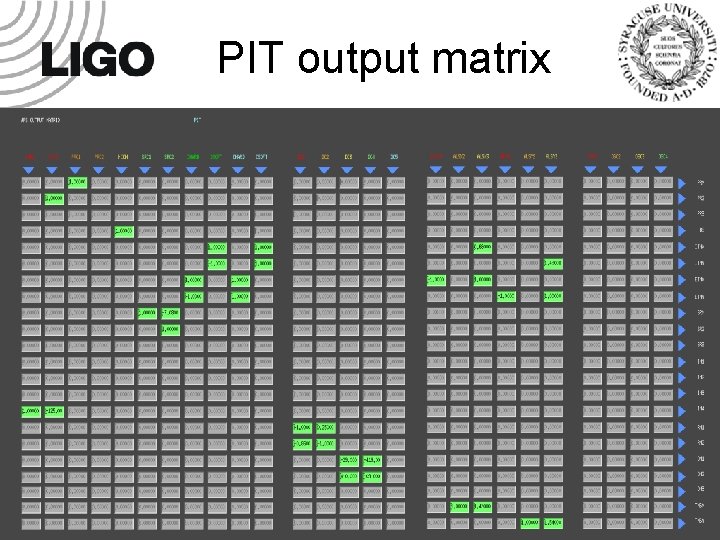
PIT output matrix
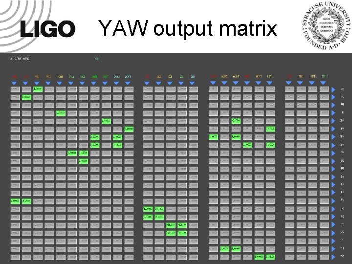
YAW output matrix
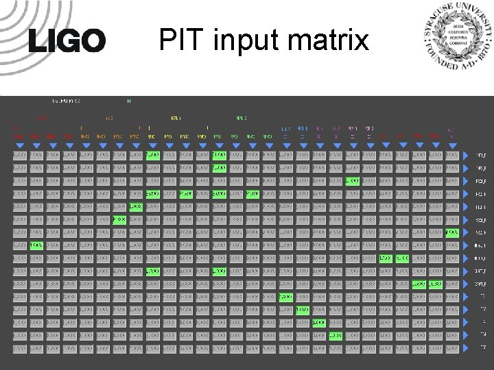
PIT input matrix
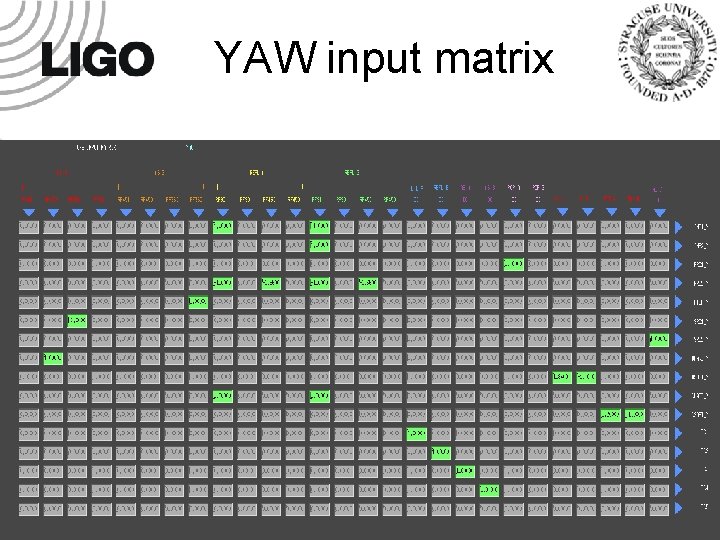
YAW input matrix
References • ISC design document – T 070236 • Modeling of Alignment Sensing and Control for Advanced LIGO – T 0900511 • L 1&H 1 ASC configuration for ER 7 – G 1500741