TCT Systems Marko Zavrtanik J Stefan Institute 2
- Slides: 20
TCT Systems Marko Zavrtanik J. Stefan Institute 2 -nd TCTW, Ljubljana, Slovenia M. Zavrtanik, 2 -nd TCT-W, Ljubljana 1
What is a TCT measurement? The answer is not simple. Deducing system properties by measuring the shape of the induced signal! • • Measuring the shape Measuring signal properties (i. e. rise time … ) Measuring the integral of the current pulse (i. e. charge). People in other fields use similar techniques but call them different. M. Zavrtanik, 2 -nd TCT-W, Ljubljana 2
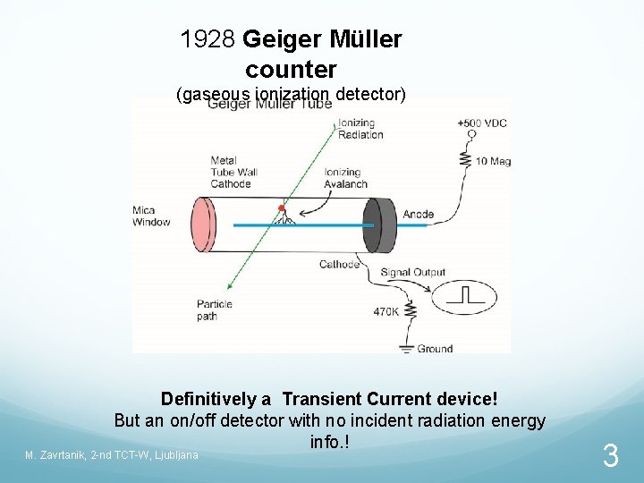
1928 Geiger Müller counter (gaseous ionization detector) Definitively a Transient Current device! But an on/off detector with no incident radiation energy info. ! M. Zavrtanik, 2 -nd TCT-W, Ljubljana 3
Technological advancements after 2 -nd WW (organic scintillators, semiconductor detectors …) gave rise to the development of: Transient Current Technique In the 1960 s observing effects of non-equilibrium carriers in different devices. For example: Experimental Results on the Information Available from the Rise Time of Pulses Supplied by the Semiconductor Particle Detector, Albergini-Quaranta, M. Martini, G. Ottaviani, G. Zanarini INFN Bologna IEEE Trans. On Nuc. Sci. , Feb. 1965 Current Injection in Solids M. Lampert, P. Mark, Academic Press, New York, 1970 M. Zavrtanik, 2 -nd TCT-W, Ljubljana 4
From 1990 s used in studies of semiconductor detectors – materials, mostly pad detectors after irradiation. For example: The Use of the Signal Current Pulse shape to Study the Internal Electric Field Profile and Trapping Effects in Neutron Damaged Silicon Detectors, E. Fretwurst ( Uni. Hamburg), H. W. Kraner, Z. Li, (BNL) NIM A 230, 1993 Development of the transient current and charge technique for the measurements of effective net concentration of ionized charges in the space charge region of p-n junction detectors V. Eremin, N. Strokana, E. Verbitskaya, (Ioffe), Z. Li, (BNL) NIM A 372, 1996 M. Zavrtanik, 2 -nd TCT-W, Ljubljana 5
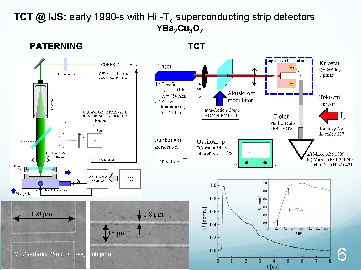
TCT @ IJS: early 1990 -s with Hi -Tc superconducting strip detectors YBa 2 Cu 3 O 7 PATERNING M. Zavrtanik, 2 -nd TCT-W, Ljubljana TCT 6
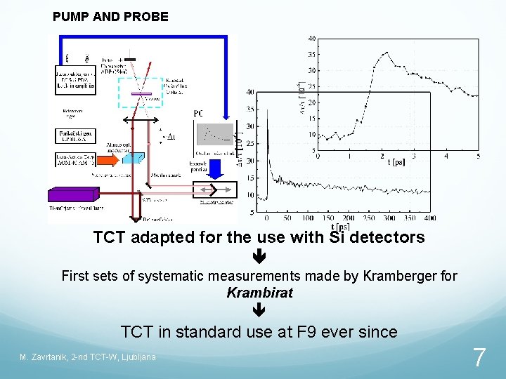
PUMP AND PROBE TCT adapted for the use with Si detectors First sets of systematic measurements made by Kramberger for Krambirat TCT in standard use at F 9 ever since M. Zavrtanik, 2 -nd TCT-W, Ljubljana 7
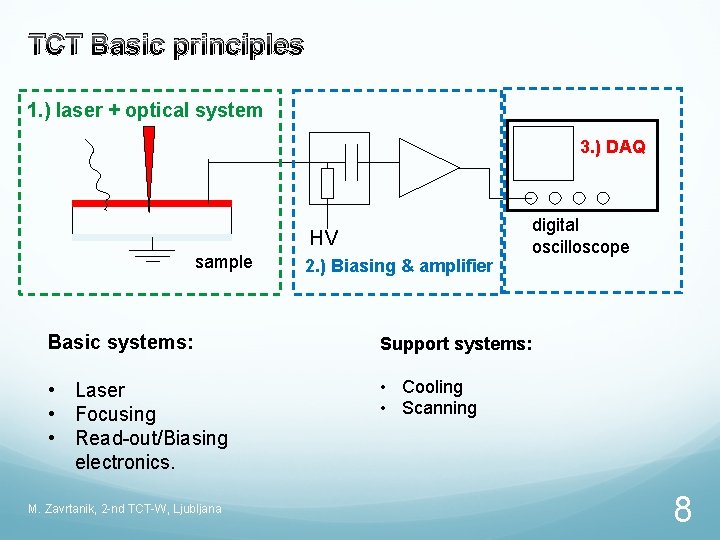
TCT Basic principles 1. ) laser + optical system 3. ) DAQ HV sample 2. ) Biasing & amplifier Basic systems: Support systems: • Laser • Focusing • Read-out/Biasing electronics. • Cooling • Scanning M. Zavrtanik, 2 -nd TCT-W, Ljubljana digital oscilloscope 8
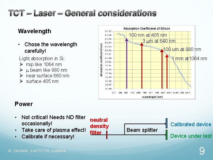
TCT – Laser – General considerations Wavelength • Chose the wavelength carefully! 100 nm at 405 nm 3 mm at 640 nm 100 υm at 980 nm Light absorption in Si: Ø mip like 1064 nm Ø m beam like 980 nm Ø near surface 660 nm Ø surface 405 nm 1 mm at 1064 nm Power • Not critical! Needs ND filter neutral occasionally! density • Take care of plasma effect! filter • Calibrate if necessary! M. Zavrtanik, 2 -nd TCT-W, Ljubljana Beam splitter Calibrated device Device under test 9
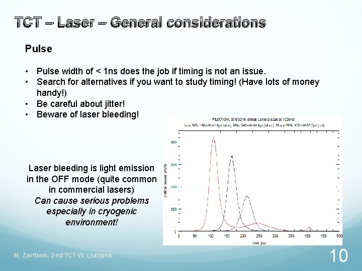
TCT – Laser – General considerations Pulse • Pulse width of < 1 ns does the job if timing is not an issue. • Search for alternatives if you want to study timing! (Have lots of money handy!) • Be careful about jitter! • Beware of laser bleeding! Laser bleeding is light emission in the OFF mode (quite common in commercial lasers) Can cause serious problems especially in cryogenic environment! M. Zavrtanik, 2 -nd TCT-W, Ljubljana 10
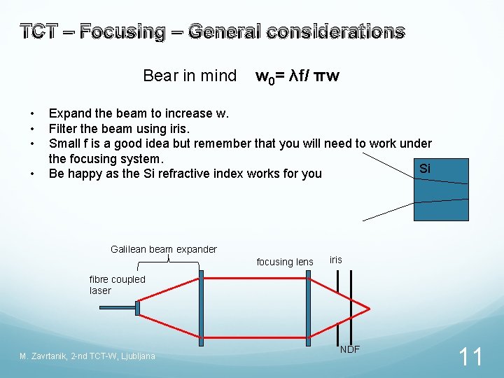
TCT – Focusing – General considerations Bear in mind • • w 0= λf/ πw Expand the beam to increase w. Filter the beam using iris. Small f is a good idea but remember that you will need to work under the focusing system. Si Be happy as the Si refractive index works for you Galilean beam expander focusing lens iris fibre coupled laser M. Zavrtanik, 2 -nd TCT-W, Ljubljana NDF 11
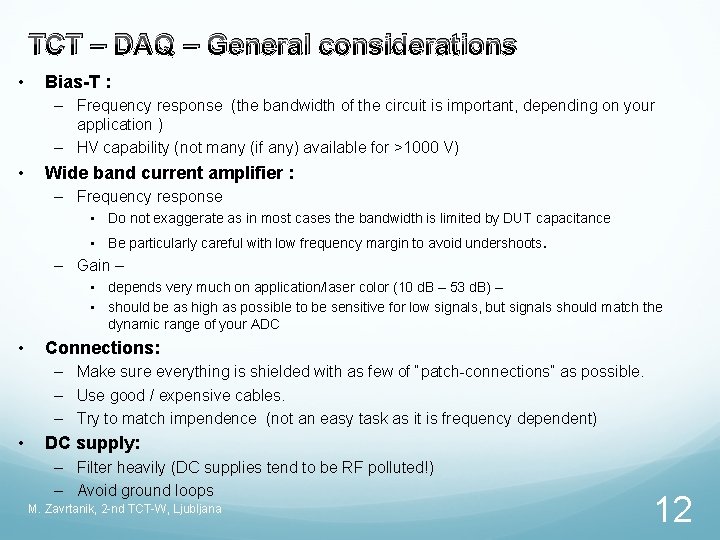
TCT – DAQ – General considerations • Bias-T : – Frequency response (the bandwidth of the circuit is important, depending on your application ) – HV capability (not many (if any) available for >1000 V) • Wide band current amplifier : – Frequency response • Do not exaggerate as in most cases the bandwidth is limited by DUT capacitance • Be particularly careful with low frequency margin to avoid undershoots. – Gain – • depends very much on application/laser color (10 d. B – 53 d. B) – • should be as high as possible to be sensitive for low signals, but signals should match the dynamic range of your ADC • Connections: – Make sure everything is shielded with as few of “patch-connections” as possible. – Use good / expensive cables. – Try to match impendence (not an easy task as it is frequency dependent) • DC supply: – Filter heavily (DC supplies tend to be RF polluted!) – Avoid ground loops M. Zavrtanik, 2 -nd TCT-W, Ljubljana 12
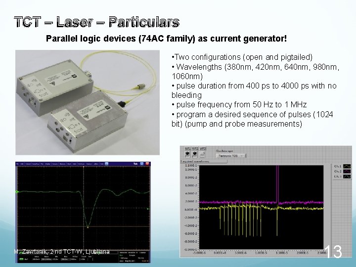
TCT – Laser – Particulars Parallel logic devices (74 AC family) as current generator! • Two configurations (open and pigtailed) • Wavelengths (380 nm, 420 nm, 640 nm, 980 nm, 1060 nm) • pulse duration from 400 ps to 4000 ps with no bleeding • pulse frequency from 50 Hz to 1 MHz • program a desired sequence of pulses (1024 bit) (pump and probe measurements) M. Zavrtanik, 2 -nd TCT-W, Ljubljana 13
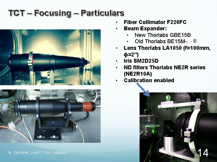
TCT – Focusing – Particulars • • • M. Zavrtanik, 2 -nd TCT-W, Ljubljana Fiber Collimator F 220 FC Beam Expander: • New Thorlabs GBE 15 B • Old Thorlabs BE 15 M-. ‐B Lens Thorlabs LA 1050 (f=100 mm, ϕ=2”) Iris SM 2 D 25 D ND filters Thorlabs NE 2 R series (NE 2 R 10 A) Calibration enabled 14
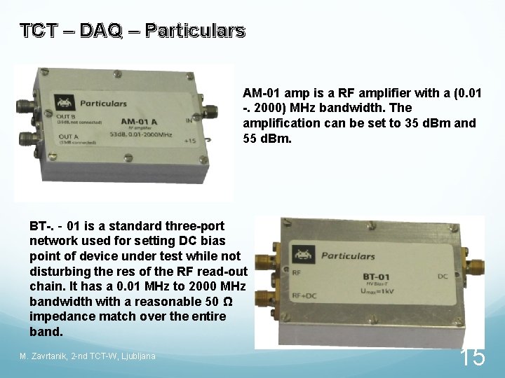
TCT – DAQ – Particulars AM-01 amp is a RF amplifier with a (0. 01 -. 2000) MHz bandwidth. The amplification can be set to 35 d. Bm and 55 d. Bm. BT-. ‐ 01 is a standard three-port network used for setting DC bias point of device under test while not disturbing the res of the RF read-out chain. It has a 0. 01 MHz to 2000 MHz bandwidth with a reasonable 50 Ω impedance match over the entire band. M. Zavrtanik, 2 -nd TCT-W, Ljubljana 15
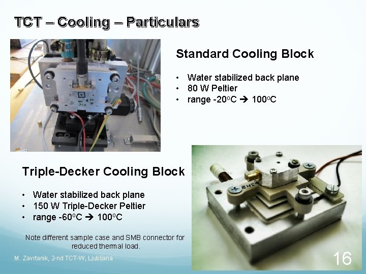
TCT – Cooling – Particulars Standard Cooling Block • Water stabilized back plane • 80 W Peltier • range -20 o. C 100 o. C Triple-Decker Cooling Block • Water stabilized back plane • 150 W Triple-Decker Peltier • range -60 o. C 100 o. C Note different sample case and SMB connector for reduced thermal load. M. Zavrtanik, 2 -nd TCT-W, Ljubljana 16
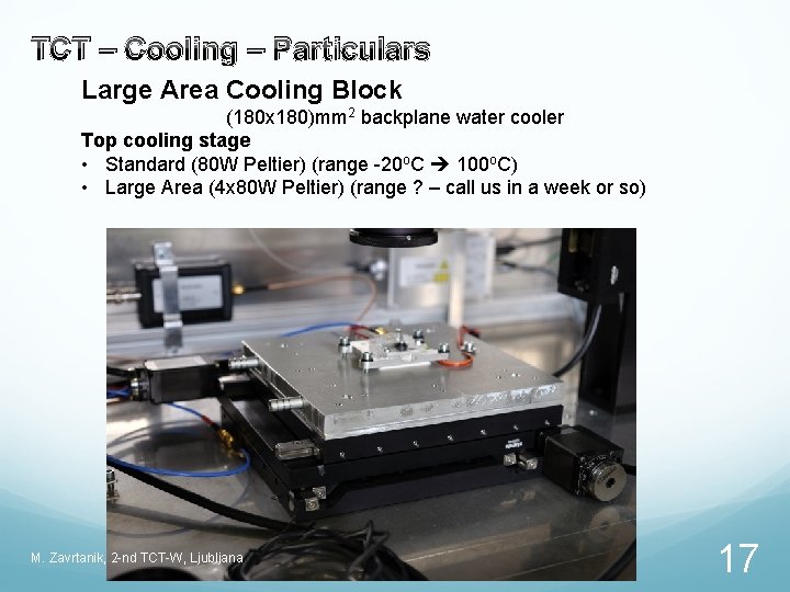
TCT – Cooling – Particulars Large Area Cooling Block (180 x 180)mm 2 backplane water cooler Top cooling stage • Standard (80 W Peltier) (range -20 o. C 100 o. C) • Large Area (4 x 80 W Peltier) (range ? – call us in a week or so) M. Zavrtanik, 2 -nd TCT-W, Ljubljana 17
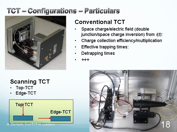
TCT – Configurations – Particulars Conventional TCT • • • Space charge/electric field (double junction/space charge inversion) from I(t): Charge collection efficiency/multiplication Effective trapping times: Detrapping times +++ Scanning TCT • Top-TCT • Edge-TCT Top-TCT Edge-TCT M. Zavrtanik, 2 -nd TCT-W, Ljubljana 18
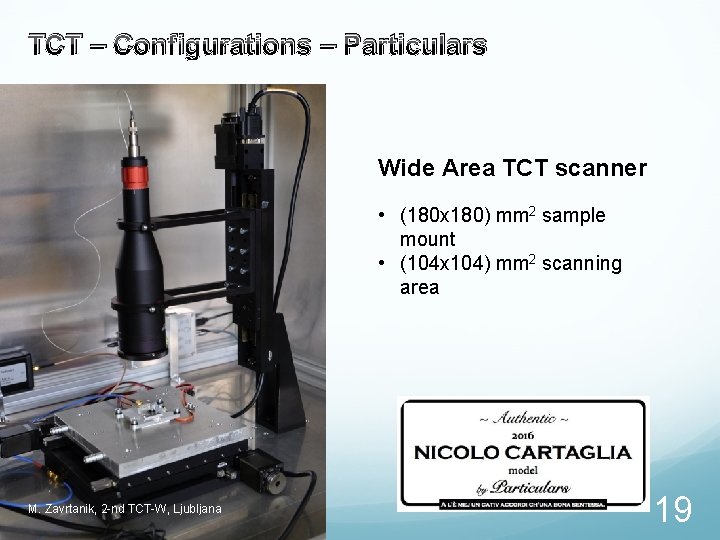
TCT – Configurations – Particulars Wide Area TCT scanner • (180 x 180) mm 2 sample mount • (104 x 104) mm 2 scanning area M. Zavrtanik, 2 -nd TCT-W, Ljubljana 19
Conclusions n TCT has been around in HEP for more than 2 decades, first as a tool used to study material properties on pad detectors. A workhorse of RD 48/50 collaborations. n Scanning-TCT systems are excellent tools to study properties of segmented detectors. Powerful analysis techniques have evolved along. n It has potential use also outside HEP and for educational purposes n Systems have become commercially available M. Zavrtanik, 2 -nd TCT-W, Ljubljana 20