Solid Oxide Fuel Cells Rodger Mc Kain Ph


 6 1 of these =")


- Slides: 29
Solid Oxide Fuel Cells Rodger Mc. Kain, Ph. D
Ion transport observed by William Grove in 1839…Based on hydrogen-oxygen, sulfuric acid electrolyte, and platinum electrodes “I cannot but regard the experiment as an important one…” William Grove to Michael Faraday October 22, 1842
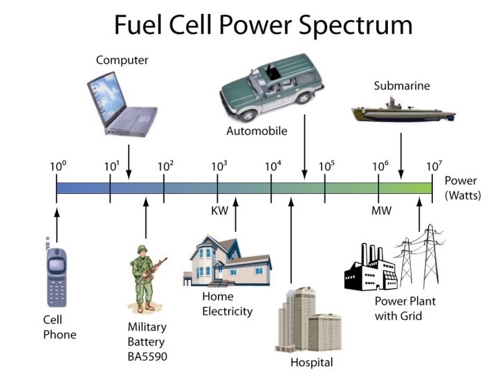
Fuel Cell – An energy conversion device that directly converts chemical energy into electrical energy (dc power). – Analogous operation to a natural gas fueled electric generator: energy in fuel and oxygen are converted to electric power as long as fuel and air are supplied. – Six types, each suited for specific applications + Heat, H 2 O
Increasing Temperature Fuel Cell Types Source: U. S. Fuel Cell Council
Attributes of Fuel Cells AFC PACF PEM MCFC SOFC Y 2 O 3 -Zr. O 2 Ceramic Electrolyte KOH Phosphoric Acid Sulfonic Acid Polymer Molten Carbonate Salt Temperature 1000 C 2000 C 1000 C 6500 C H 2 H 2/CO 55% 40% Very low Difficult 60% 35% Very low Difficult 55% 50% Low Yes Moderate Fast Slow Fuel Efficiency (H 2 fuel) (NG fuel) Pollution Hydrocarbon Fuel Use Start-Up 60% -Very low No Fast 800 -10000 C
Fuel Cell Stacks • Operating voltage of a single cell is ~0. 7 volts • Cells are “stacked” in series to increase voltage to useful levels: Source: U. S. Fuel Cell Council
Fuel Cell Power System Useful heat Heat Management Fuel Air Fuel Processor Fuel cell Stack Sub Assembly Controls Power Conditioner 10 k. W
High Efficiency
High Efficiency at Part Load
Low Emissions Average U. S. Utility Emissions ONSI PC 25 200 k. W NG Fuel Cell (lbs per megawatthour) (lbs per megawatt-hour) Nitrogen Oxides 7. 65 0. 016 Carbon monoxide 0. 34 0. 023 Reactive organic gases 0. 34 0. 0004 Sulfur oxides 16. 1 0 Particulates (PM 10) 0. 46 0 Contaminant
Solid Oxide Fuel Cells • Based upon ion conductivity of certain ceramic materials at elevated temperatures (>600 C) – – First observed by Nernst in 1890’s Fluorite Structures (e. g. yttria stabilized zirconia) Face Centered cubic arrangement Transport through crystal lattice vacancies and oxide ions located between crystal faces – First SOFC constructed in 1937 by Baur and Preis • Requires porous electrodes and dense electrolyte, low electronic conductivity, and high strength
RL O 2 + 4 e- 2 O 2 Pt Ink v A Anode catalyst layer CH 4 + 3 O 2 - CO 2 + H 2 O + 2 e. Effluent Pt Wire Fuel/CH 4 Cathode catalyst layer Electrolyte Disc Yttrium-stablized Zirconia (>950 °C) Galladium-doped Ceria (>600°C) CH 4 + CO 2 CH 4 + H 2 O CO + H 2 O CH 4 + 0. 5 O 2 A Oad Products CH 4 Oad CO, H 2, CO 2, H 2 O Cn. H 2 n Oad Cn. H 2 n. O, CO 2, H 2 O C Oad CO 2 2 CO + 2 H 2 CO 2 + 3 H 2 CO 2 + H 2 CO + 2 H 2 T (°C) 600 -1200 550 -950
Relationship between fuel processing and fuel cells
Basis for Fuel Cell Operation • Electron transfer – chemical reaction – Voltage determined by difference in chemical potential of fuel and oxygen – Current determined by area of cell • Catalyzed conversion of oxygen and hydrogen into reactive species O= and H – H 2 + O 2 = H 2 O + 2 electrons + heat • Electrons are separated from reactants by circuit • Need to understand electrical circuit background as it relates to fuel cell
Electric terms 6, 240, 000, 000 electrons / sec = 1 amp Current is the flow of electrons Fuel Cell Stack Low resistance Volts Copper wire, 1/16” diameter, 10 amps, electrons travel 1 cm In 28 seconds. High resistance Resistance If h is 1 volt and current is 1 amp Resistance is 1 ohm
What’s a watt? Work involves height lifted and weight of ball, ft-lbs Work has no time limit, power does 550 ft-lbs/sec = 1 horsepower = 746 watts Power = (height lifted times weight of ball) times (balls per second), or Power = voltage times current, Watts = volts times amps
Energy flow Heat Food Air Work, power Same story for electric system Food anode, Air cathode Stack produces power and heat Heat In a perfect system all the energy in the food would be converted to power. Actually, only part is converted which defines the efficiency. All the energy in the food eventually appears as heat.
V-I scan 10 ASR is the slope of the dashed red line 8 Height lifted or volts (V) 6 4 2 0 0 10 20 30 40 Balls lifted per hour, or amps (I) 50
V-I scan 10 8 Height lifted or volts (V) 6 1 of these = 2 of these! 4 2 0 0 5 10 15 20 Balls lifted per hour, or amps (I) 25
Micro view - Electric Icon Via Bond Layer Porous Bond Layer e- e- O= Fuel layer #1 e- e- O= O= O= e- e- e- Air layer #1 O= Anode Electrolyte* Cathode O= + H 2 = 2 e- +H 2 O e- ½ O 2 + 2 e- = O= e- + Fuel utilization Air Stoics *A nonmetallic electric conductor in which current is carried by the movement of ions.
Complete micro view Icon Fuel Flow, H 2 O+CO H 2+CO 2 Bond Layer CO CO 2 e- CO CO Porous CO 2 O= N 2 Bond Layer H 2 O N 2 CO CO 2 CO e- N 2 N 2 O 2 Air Flow, O 2 + N 2 Fuel layer #1 e- e- e- N 2 CO O= O= O= N 2 - N 2 N 2 e- N 2 Air layer #1 O= N 2 e- + Via Anode Electrolyte Cathode O= + H 2 = 2 e- +H 2 O ½ O 2 + 2 e- = O=
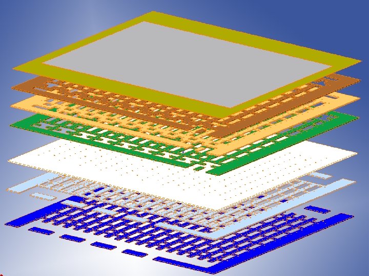
Co-flow Design Concept – Unit Cell Multi-layer ceramic construction Vias carry current Cell Air flow Fuel flow
Interconnect Sealant Ink “bumps” printed on vias Thermocouples, Voltage taps
Add a cell Thermocouples, Voltage taps
Manifold arrangement Fuel inlets Manifold Air inlets Gasket
Vehicle ICE vs. Fuel Cell Direct Drive Efficiency Comparison 40 100 Energy Units IC Engine 40% Power Train 37. 5% 20 Idling 60 15 5 Friction 20 40 Energy Units Fuel Cell 50% 20 Direct Drive 75% 0 Idling 5 Friction 15
Summary • Fuel Cells have been around a long time • They present the potential to be highly efficient because of direct conversion of chemical energy to electrical energy • Solid oxide fuel cells are based upon ion conducting properties of ceramic materials like doped zirconia • Temperatures above 600 C are required for operation • To be viable fuel cells must have high power per area, and operate with low cost materials