SingleDish Radio Telescopes Dr Ron Maddalena National Radio


 Offset Pointing: (90 min) Continuous Tracking: (30 min)")


- Slides: 49
Single-Dish Radio Telescopes Dr. Ron Maddalena National Radio Astronomy Observatory Green Bank, WV
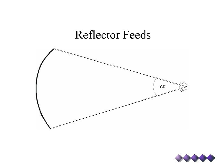
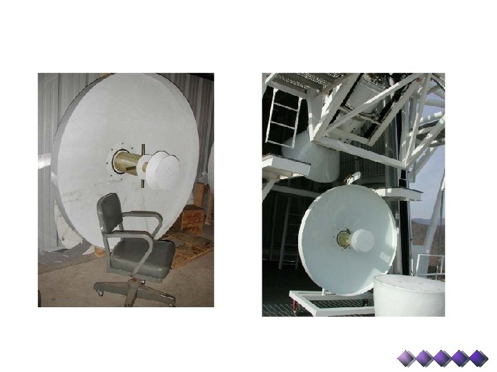
Telescope Optics Prime Focus: Retractable boom Gregorian Focus: 8 -m subreflector - 6 -degrees of freedom
Telescope Structure Ø Fully Steerable Ø Elevation Limit: 5º Ø Can observe 85% of the entire Celestial Sphere Ø Slew Rates: Azimuth - 40º/min; Elevation - 20º/min
Telescope Structure Blind Pointing: (1 point/focus) Offset Pointing: (90 min) Continuous Tracking: (30 min)
Telescope Structure
Active Surface Deformations from Finite Element Model
Active Surface
Telescope Optics Rotating Turret with 8 receiver bays
Receivers Receiver Operating Range Status Prime Focus 1 0. 29— 0. 92 GHz Commissioned Prime Focus 2 0. 910— 1. 23 GHz Commissioned L Band 1. 15— 1. 73 GHz Commissioned S Band 1. 73— 2. 60 GHz Commissioned C Band 3. 95— 5. 85 GHz Being Upgraded X Band 8. 2— 10. 0 GHz Commissioned Ku Band 12. 4— 15. 4 GHz Commissioned K Band 7 -pixel 18— 26. 5 GHz Commissioned Ka Band 26— 40 GHz Commissioned Q Band 40— 50 GHz Commissioned W Band 68— 92 GHz Commissioned Penn Array 86— 94 GHz Being Upgraded
Typical Components Amplifiers Splitters Mixers Couplers Attenuators Power Detectors Synthesizers Filters Switches Multipliers
Types of Filters Edges are smoother than illustrated
Types of Mixers f f. IF f. LO f. IF = n*f. LO + m*f • n and m are positive or negative integers, usually 1 or -1 • Up Conversion : f. IF > f • Down Conversion : f. IF < f • Lower Side Band : f. LO > f - Sense of frequency flips • Upper Side Band : f. LO < f
Example Switches
40 -Ft System
Quiz 1: Determine values for the first LO for the 40 -ft when… • Observing HI at 1420. 41 MHz • Observing OH at 1665. 6 MHz
Receiver Room
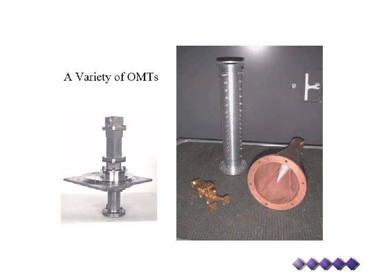
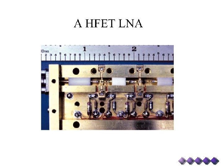
Typical Receiver
Multi-beam Receiver
Local Oscillator and Switching Matrix
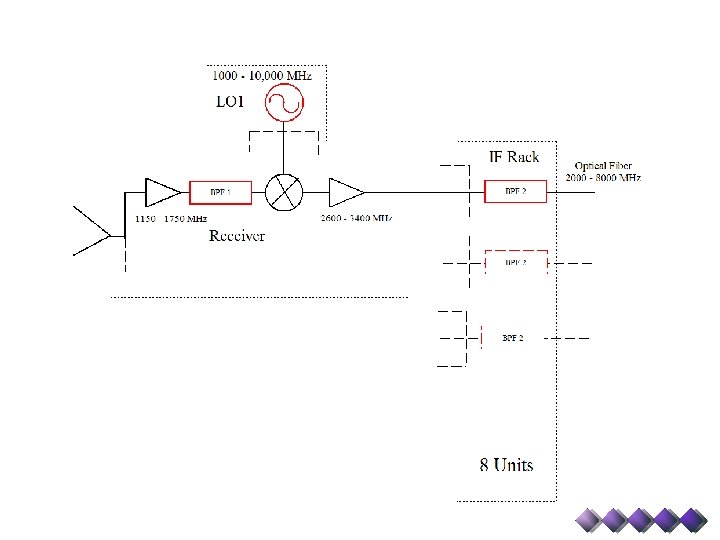
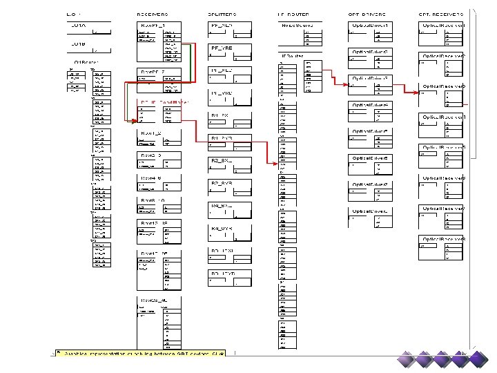
IF Rack – Input switching Matrix, IF Filters, Power Balancing Attenuators, and Drivers for 8 Optical Fibers
Power Balancing/Leveling and Non. Linearity
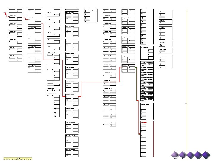
Converter and Analog Filter Racks, Spectrometer
Converter Rack – Receivers for Optical Fibers, LO 2 and LO 3, Power Balancing Attenuators, Output Switches to Backends and AFR
Analog Filter Rack For 12. 5 and 50 MHz Slow-Speed Spectrometer Samplers : LO 4 and Filters For 200 and 800 MHz High-Speed Spectrometer Samplers : Input Switches and Filters.
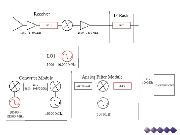
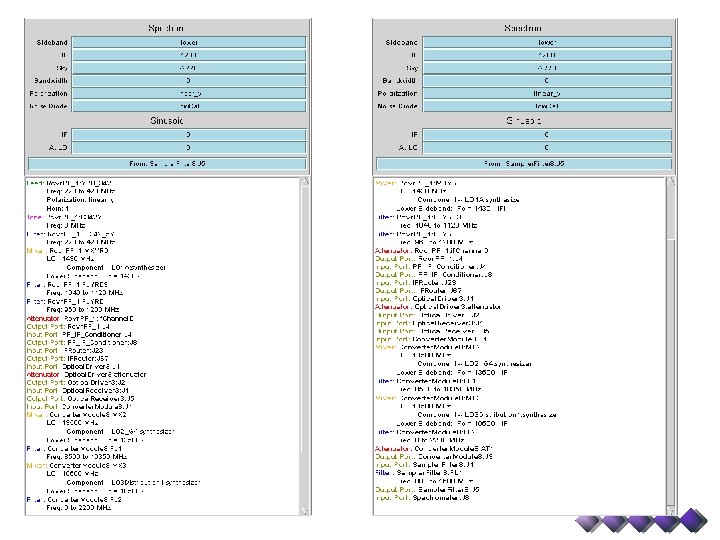
Quiz 2: Determine values for red components
Quiz 2: Determine values for red components • Goal : Observe simultaneously 1420 MHz and 1665 MHz with the 50 MHz wide (75 MHz center frequency) mode of the Spectrometer • Parameters: o BPF 1 can be: 1100– 1800, 1600 -1750, 1300 -1450, or 1100 -1450 MHz o All mixers are LSB. Hint: first two mixers up convert, the last two down convert. o BPF 2 can be : 2990 -3010, 2960 -3040, 2840 -3160, 2360 -3640, 5960 -6040, 5840 -6160, or 5360 -6640 MHz o BPF 3 can be : 50 -100 or 25 -37. 5 MHz o See block diagram for other parameters • Hint: Work from the receiver down the chain until you get stuck, then from Spectrometer up. Try 1420 MHz first, then add in 1665 MHz. • Record values for LO 1 and both LO 2’s; settings for BPF 1, 2, and 3; and values for all Intermediate Frequencies.
GBT – Astrid does all the hard work for you…. . config. Line = """ receiver = "Rcvr 1_2" beam = “B 1" obstype = "Spectroscopy" backend = "Spectrometer" nwin =2 restfreq = 1420. 4058, 1665. 0 deltafreq = 0, 0 bandwidth = 12. 5 swmode = "tp" swtype = "none" swper = 1. 0 swfreq = 0. 0, 0. 0 tint = 30 vlow =0 vhigh = 0 vframe = "lsrk" vdef = "Radio" noisecal = "lo" pol = "Linear" nchan = "low" spect. levels = 3 """
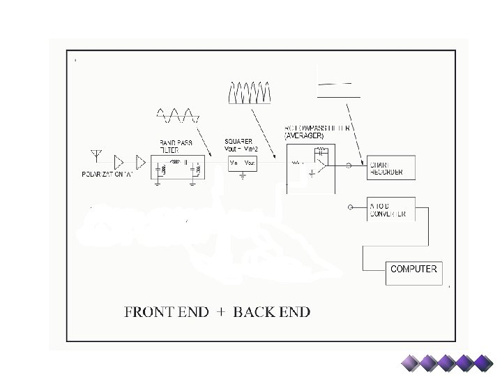
Model Receiver
Continuum - Point Sources On-Off Observing • Observe blank sky for 10 sec • Move telescope to object & observe for 10 sec • Move to blank sky & observe for 10 sec • Fire noise diode & observe for 10 sec • Observe blank sky for 10 sec
Continuum - Point Sources On-Off Observing
Continuum - Point Sources On-Off Observing • Known: • Desired: • Equivalent temperature of noise diode or calibrator (Tcal) = 3 K • Bandwidth (Δν) = 10 MHz • Gain = 2 K / Jy • Antenna temperature of the source (TA) • Flux density (S) of the source. • System Temperature(Ts) when OFF the source • Accuracy of antenna temperature (σ TA)