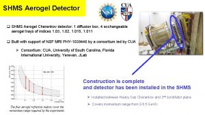
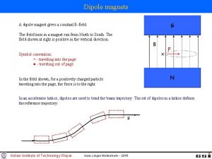
SHMS Cryogenics and Q 2Q 3 Dipole Cool


- Slides: 23

SHMS Cryogenics and Q 2(Q 3 Dipole) Cool Down Paul Brindza October 12, 2016 10/24/2020 Hall C SHMS Q 2 Q 3 Dipoel ERR Review 1

Cryogenics Top level • Cryogenic System is common to JLAB Halls A, B and C • All Halls are superconducting • End Station Refrigerator(ESR) 1500 Watts • Hall A- HRS right and HRS left( 1994) • Hall B – Clas 12 Torus and Solenoid(2016) • Hall C – HMS( 1992)and SHMS( 2016) 10/24/2020 Hall C SHMS Q 2 Q 3 Dipoel ERR Review 2

End Station Cryogenics 10/24/2020 Hall C SHMS Q 2 Q 3 Dipoel ERR Review 3

ESR Helium Refrigerator System • ESR system – Completely automated system runs 24/7 unattended – 1500 watts capacity – 10, 000 liter LHE local storage – 10, 000 gallon LN 2 local storage – 250, 000 gallon gas Helium local storage – Purifiers- LN 2 charcoal scrubbers – Cold and warm Connection to Central Helium Liquifier(CHL) for extra capacity and inventory – Transfer lines deliver LHE and LN 2 to Hall A, B and C 10/24/2020 Hall C SHMS Q 2 Q 3 Dipoel ERR Review 4

Hall C Cryogenic System I • Transfer Line from ESR – LHE supply and return – LN 2 supply – 20 K He gas supply – 25 K Gas Helium return • Gas supply and return line to ESR – 3. 5 Atm gas Helium supply – Vapor cooled lead He gas return line – Warm He return line for cool downs – Exhaust N 2 gas vent line to atmosphere 10/24/2020 Hall C SHMS Q 2 Q 3 Dipoel ERR Review 5

Hall C Cryogenic System II • HMS system ( 1993) – Cools 4 SC magnets( Q 1, Q 2, Q 3 & Dipole) – Flex line to permit rotations – HMS distribution XFER line- parallel supply/return – HMS gas return lines • SHMS system( 2014) – Cools 5 SC magnets (HB, Q 1, Q 2, Q 3 & Dipole) – Flex line to permit rotations – SHMS distribution XFER line-parallel supply/return – SHMS gas return lines • Hall C magnet reservoirs have min. 1 hour hold time 10/24/2020 Hall C SHMS Q 2 Q 3 Dipoel ERR Review 6

Hall C Cryogenics III • Hall C Cryo-Target system – Cools local Hall C cryo-target-3 @ 800 watts – Local valve box to select LHE or 20 K HE cooling – LH 2, LD 2 targets at ~ 20 K – HE 3 gas targets at 4. 2 K • Hall C Moller Polarimeter- beam polarization – 5 tesla SC solenoid to polarize iron foils – Transfer line for LHE and LN 2 – Gas return lines 10/24/2020 Hall C SHMS Q 2 Q 3 Dipoel ERR Review 7

Hall C Cryogenics “block” diagram ESR Hall C Distribution SHMS Transfer Line Q 1 Q 2 Q 3 D HB Q 1 Q 2 Target Q 3 D Moller

SHMS Cryogenic Schematics

SHMS Magnet Cooling System • • Distribution transfer line on SHMS All magnets cooled in parallel independently Internal Cool Down/Warm Up Heat Exchanger He supply at 2. 5 Bar 4. 5 K He return at 1. 2 Bar and 4. 4 K LN 2 supply 80 K , 3. 5 Bar Cool down He gas 3. 5 Bar ( 250 K to 80 K) 10/24/2020 Hall C SHMS Q 2 Q 3 Dipoel ERR Review 10

SHMS Distribution System 10/24/2020 Hall C SHMS Q 2 Q 3 Dipoel ERR Review 11

Q 2 Magnet P&I

SHMS Cool Down Control Screens 10/24/2020 Q 2 Q 3 D ERR Review October 12, 2016 13

Hall C Magnet Cool Down I • 300 K to 80 K cool down – Process uses a Hall C Heat Exchanger under local PLC control using sensors in subject magnet – Blends 80 K He and 300 K He to make any temperature cold He gas between 250 K and 80 K – Process makes 10 Grams/sec cold Helium – Consumes 30 Grams/sec LN 2 when output Temp is 80 K – PLC manages LN 2 supply, coolant Temp and interlocks – Coolant is 50 K < Magnet temp, Magnet gradients < 50 K – Coolant distributed to subject magnet ( HB, Q 1, Q 2, Q 3, Dipole) – Q 2 Q 3 take 2 weeks(14 days) Dipole takes 3 weeks(21 days) 10/24/2020 Hall C SHMS Q 2 Q 3 Dipoel ERR Review 14

Cool Down 300 K to 80 K

Hall C Cool Down Heat Exchanger 10/24/2020 Hall C SHMS Q 2 Q 3 Dipoel ERR Review 16

SHMS Q 1 Cool Down #2 Q 1 cool down #1 300. 00 ~11 Day Cool down Cool Down limited by coolant flow being restricted by reduced range of JT valve stroke. Corrected after magnet was warm up. 250. 00 200. 00 T (K) Maintained <50 K temperature differential 8 day Cool Down period 150. 00 100. 00 Heat Exchanger off Lost one day over the weekend 50. 00 7/30 0. 00 2/17 2/19 2/21 2/23 2/25 2/27 Date - Time 3/1 3/3 3/5 8/1 8/3 Date - Time 8/5 8/7

Hall C Magnet Cool Down II • Entire process is managed by PLC – Magnet Temp below 100 K – Introduce LHE at 4. 4 K thru “bottom fill” valve in each magnet – Internal manifold distributes LHe to far end of each magnet – Magnet cools to 4. 4 K and starts accumulating LHE – LHE rises into reservoir and registers on LL probe – Cooling switches to top fill – LHE switches to cold return • Operator tunes up PID liquid level regulation 10/24/2020 Hall C SHMS Q 2 Q 3 Dipoel ERR Review 18

Cooldown to 4 K

Top Fill / Cold Return

Cool Down Logic

Cool Down Interlocks / Controls Event Action Magnet Temperature Delta > 50 K Close Supply valve Temperature gradient between HX output and magnet input > 50 K Adjust HX output temperature set point, Close Supply valve to magnet. Helium Pressure to High Close Supply Valve, open warm Valve. Helium Pressure below 1 atm Interlock Insulating Vacuum Bad Interlock Support Links out of range Close Supply Valve. Adjust tension on links. Flow to Hall C exceeds ESR set point by 0. 5 g/s Close supply Valve Helium Cold Return temperature > 6 K Close cold return valve, open warm return valve

Cryogenics and Cool Down Summary • Hall C cryogenics in continuous service since 1993 for HMS • SHMS cryo in continuous service since 2014 • Cool Down(CD) System has been in continuous use since 1993 • CD System has been copied by Halls A, B and D • PLC controls are very mature and have been in continuous service for 15 years 10/24/2020 Hall C SHMS Q 2 Q 3 Dipoel ERR Review 23
 Dipole dipole vs ion dipole
 Induced dipole
 Dipole induced dipole forces
 Dispersion forces vs dipole dipole
 Dipole induced dipole forces examples
 Intermolecular forces in dimethyl ether
 Ion induced dipole example
 Dipole dipole bond
 Intermolecular forces present in hbr
 Dipole-dipole attractions
 Dipole dipole interaction example
 Vapor pressure intermolecular forces
 Intermolecular forces hydrogen bonding
 Instantaneous dipole moment
 Mpez geo app
 Transfer to shms
 Cryogenics palm harbor
 Eleet cryogenics
 Katherine is very interested in cryogenics
 Practical cryogenics
 Gde
Gde Sps cryogenics
 Dipole meaning in chemistry
 Ch2cl intermolecular forces
