SEQUENCE DIAGRAM PART 1 WHAT IS A SEQUENCE
")


 Caller Phone Recipient Picks up Dial tone Dial")


- Slides: 23
SEQUENCE DIAGRAM (PART 1)
WHAT IS A SEQUENCE DIAGRAM? Sequence diagrams, commonly used by developers, model the interactions between objects in a single use case. They illustrate how the different parts of a system interact with each other to carry out a function, and the order in which the interactions occur when a particular use case is executed.
UML SEQUENCE DIAGRAMS • Describe the flow of messages, events, actions between objects • Show concurrent processes and activations • Show time sequences that are not easily depicted in other diagrams • Typically used during analysis and design to document and understand the logical flow of your system Emphasis on time ordering!
A sequence diagram is structured in such a way that it represents a timeline which begins at the top and descends gradually to mark the sequence of interactions. Each object has a column and the messages exchanged between them are represented with arrows. • • Object Lifeline Notation Activation Bars Message Arrows
SEQUENCE DIAGRAM (MAKE A PHONE CALL) Caller Phone Recipient Picks up Dial tone Dial Ring notification Picks up Hello *This Sequence Diagram is to demonstrate a non-online system merely to give you some idea
TERMS AND CONCEPTSOBJECTS/PARTICIPANTS The sequence diagram is made up of collection of participants or objects. Participants are system parts that interact each other during sequence diagram. The participants interact with each other by sending and receiving message The object is represented by as below: Object
LIFELINE Lifeline represents the existence of an object over a period of time. It is represented by vertical dashed line. So, these objects are aligned at top of diagram with their lifeline from top to bottom of diagram. STUDENT
ACTIVATION BAR It shows the period of time during which an object is performing an action. The top of rectangle is aligned with start of the action. The bottom is aligned with its completion and can be marked by a written message It is represented by tall thin rectangle:
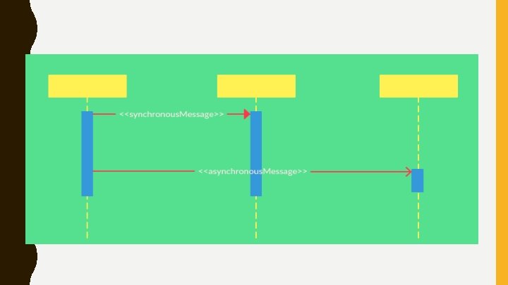
MESSAGES The interaction in a sequence diagram between the objects can be shown by using messages. The messages on sequence diagram are specifies using an arrow from participant that wants to pass the messages to the participant that receive the messages. Messages can be flow in whatever direction required for interaction from left to right and right to left.
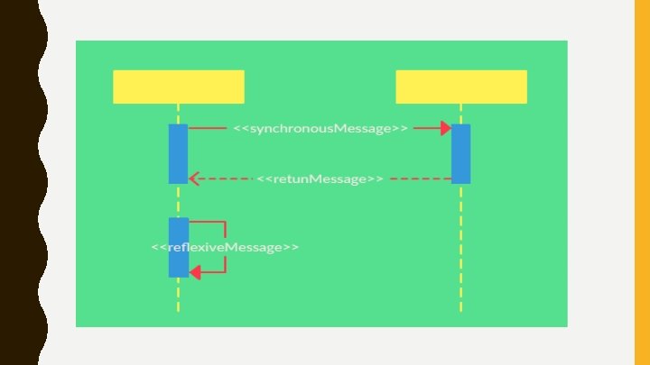
A synchronous message is used when the sender waits for the receiver to process the message and return before carrying on with another message ONE BY ONE; WAITS FOR ONE TO COMPLETE An asynchronous message is used when the message caller does not wait for the receiver to process the message and return before sending other messages to other objects within the system SIMULTANEOUS
Reflexivemessages: * If the object sends the message to itself then it is called as ‘Reflexive message. *It is represented by solid line with loops the lifeline of object. Return messages: - * It can be used at the end of activation bar to show that control flow of activation returns to the participant that pass the original message. *It is represent by dashed line from sender to receiver.
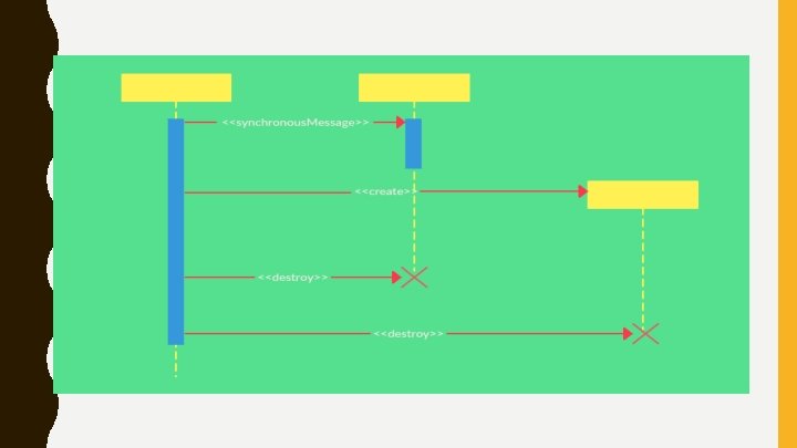
Create messages: - * It is used to create object during interaction. * The object can be created by using <<create>> to indicate the timing of creation. * Creating message can be shown as below: Destroy messages: - * It is used to destroy the objects during interaction. * The objects can be terminated using <<destroy>> which points to an “x”. * It indicates that object named message is terminated.
*MORE EXPLANATION ABOUT CREATION AND DESTRUCTION MESSAGE • Participant creation message; objects can be created in the middle of a sequence. The dropped participant box notation is used when you need to show that the particular participant did not exist until the create call was sent. • Participant destruction message; participants, when no longer needed, can also be deleted from a sequence diagram. This is done by adding an ‘X’ at the end of the lifeline of the said participant.
Time: - The sequence diagram describes the order in which interaction takes place. So time in an important factor. The time on sequence diagram starts at top of the page just below the object and then progress down the page. Time is all about ordering but not duration.
SEQUENCE DIAGRAM OF RAILWAY RESERVATION SYSTEM
Example: Use case example Create new online library account
From the use case diagram example of ‘Create New Online Library Account’, we will focus on the use case named ‘Create New User Account’ to draw our sequence diagram. Step 1 Identify the objects or participants in the use case ‘Create New User Account’ • • Librarian Online Library Management system User credentials data base Email system
STEP 2 List down the steps involved in the execution of the use case • The librarian requires the system to create a new online library account • The librarian selects the library user account type • The librarian enters the user’s details • The user’s details are checked using the user Credentials Database • The new library user account is created • A summary of the new account’s details is emailed to the user
STEP 3 Identify which messages should be passed between the objects we identified earlier as the system executes these steps. Then draw the sequence diagram.
SEQUENCE DIAGRAM EXAMPLE OF AN ONLINE MOVIE TICKET BOOKING SYSTEM