SAE Aero Design East 2005 University of Cincinnati


- Slides: 33

SAE Aero Design® East 2005 University of Cincinnati Aero. Cats Team #039 Design Team Todd Barhorst Matthew Crummey John Louis John Vandenbemden David Chalk Matthew Goettke James Mount Steven J. Coppess Kevin Harsley Alex Sullivan

Outline l l l l Basic Configuration Aerodynamics Structural Design Weights & Balance Stability & Controls Propulsion Performance & Optimization Conclusion

Basic Configuration l Box Wing Span limitation dictates two wings, for greater planform area – Winglets draw vortices away from the wingtips, improving wing efficiency – Minimizes induced drag – Provides optimal Oswald span efficiency factor – Example values for gap/span ratio of 0. 2 l Traditional Tail – – Relatively lightweight Easy to construct

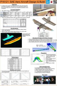
Aerodynamics: Design Refinement l TORNADO code used to analyze aerodynamics – l Based upon Vortex Lattice Theory Wing gap – Gap-to-span ratio set to 0. 6 l l Due to practical limitations Forward stagger (15 in) Fuselage accessibility – Minimal efficiency impact – l Tapered winglets Decreased weight – Decreased side area – l Improved lateral stability Negligible effect on performance Final wing efficiency: e = 2. 2

Aerodynamics: Main Wing Airfoil l Application High Lift – Low Reynolds Number – l l Re = 300, 000 Modified Eppler E 423 – Advantages Relatively small moment l Ease of construction l – Modifications De-cambered by 25% l Improved drag polar, higher L/D l l 2 D Analysis performed with XFOIL Cl. Max 1. 8 Cm -0. 187

Aerodynamics: Horizontal & Vertical Tail Airfoil Re = 300, 000 • NACA 0014 − Relatively High CL – Allows for smaller elevator – Produces minimal CD throughout operating conditions • 2 D XFoil Data • Widest of Drag Buckets Viewed

Aerodynamics: Wind Tunnel Testing (Main Airfoil) l l Wind-tunnel airfoil testing – Conducted @ UC Instrumentation – Differential Pressure Sensor Experimental vs. Published Data l - Tunnel Data Verified l Test Conditions – Re: 200, 000 – 400, 000 – AOA: -4º – 17º Flight Telemetry Package – AOA Probe – Pitot-Static Probe – RPM Sensor – Temperature Sensor

Aerodynamics: Lift vs. Alpha & Drag Buildup Stall Lift Off Max L/D 3 D Wing Total A/C Trim Max Climb Angle Total Drag 3 D Wing Horizontal Tail Lift Off Max L/D Max Climb Angle Vertical Tail Fuselage

Aerodynamics: Drag Polar & Lift-to-Drag Stall Max Climb Angle Max L/D Lift Off Max L/D Total A/C Trim 3 D Wing Max Climb Angle S t 3 D Max Lift 3 D a Wing Clim Off l Wi Lift b l Tot ng Off Angl Stall al e Total A/C Trim A/C Total A/C Trim

Structural Design: Airfoil Construction l Semi-monocoque construction method – l Utilized for all airfoils (wings, winglets, and tails) Components: – Composite-reinforced spars l Spar caps: Graphlite © carbon fiber rods – High strength-to-weight ratio – Main load-bearing members l Fiberglass shear web – Balsa wood ribs l Lightweight l Secondary members – Front portion of D-spar l Fiberglass skin – Monokote skin

Structural Design: Airfoil Construction l Semi-monocoque construction method – l Utilized for all airfoils (wings, winglets, and tails) Components: – Composite-reinforced spars l Spar caps: Graphlite © carbon fiber rods – High strength-to-weight ratio – Main load-bearing members l Fiberglass shear web – Balsa wood ribs l Lightweight l Secondary members – Front portion of D-spar l Fiberglass skin – Monokote skin

Structural Design: Airfoil Construction l Semi-monocoque construction method – l Utilized for all airfoils (wings, winglets, and tails) Components: – Composite-reinforced spars l Spar caps: Graphlite © carbon fiber rods – High strength-to-weight ratio – Main load-bearing members l Fiberglass shear web – Balsa wood ribs l Lightweight l Secondary members – Front portion of D-spar l Fiberglass skin – Monokote skin

Structural Design: Airfoil Construction l Semi-monocoque construction method – l Utilized for all airfoils (wings, winglets, and tails) Components: – Composite-reinforced spars l Spar caps: Graphlite © carbon fiber rods – High strength-to-weight ratio – Main load-bearing members l Fiberglass shear web – Balsa wood ribs l Lightweight l Secondary members – Front portion of D-spar l Fiberglass skin – Monokote skin

Structural Design: Airfoil Construction l Semi-monocoque construction method – l Utilized for all airfoils (wings, winglets, and tails) Components: – Composite-reinforced spars l Spar caps: Graphlite © carbon fiber rods – High strength-to-weight ratio – Main load-bearing members l Fiberglass shear web – Balsa wood ribs l Lightweight l Secondary members – Front portion of D-spar l Fiberglass skin – Monokote skin

Structural Design: Airfoil Construction l Semi-monocoque construction method – l Utilized for all airfoils (wings, winglets, and tails) Components: – Composite-reinforced spars l Spar caps: Graphlite © carbon fiber rods – High strength-to-weight ratio – Main load-bearing members l Fiberglass shear web – Balsa wood ribs l Lightweight l Secondary members – Front portion of D-spar l Fiberglass skin – Monokote skin

Structural Design: Fuselage l Semi-monocoque construction method l Components – Bulkheads l Carbon fiber l High strength, lightweight l Provides attach points – Skin l Fiberglass l Formed on full-scale foam model l Lightweight – Stringers l Graphlite © rods l Embedded in skin

Structural Design: Fuselage l Semi-monocoque construction method l Components – Bulkheads l Carbon fiber l High strength, lightweight l Provides attach points – Skin l Fiberglass l Formed on full-scale foam model l Lightweight – Stringers l Graphlite © rods l Embedded in skin

Structural Design: Fuselage l Semi-monocoque construction method l Components – Bulkheads l Carbon fiber l High strength, lightweight l Provides attach points – Skin l Fiberglass l Formed on full-scale foam model l Lightweight – Stringers l Graphlite © rods l Embedded in skin

Structural Design: Fuselage l Semi-monocoque construction method l Components – Bulkheads l Carbon fiber l High strength, lightweight l Provides attach points – Skin l Fiberglass l Formed on full-scale foam model l Lightweight – Stringers l Graphlite © rods l Embedded in skin

Structural Design: Landing Gear l l Main gear struts – Laminar composite construction l Stacked Graphlite © rods l Wrapped with woven carbon fiber fabric – Analysis l Stress & deflection calculations l Experimental testing Other components – – Spring steel front gear Alumimum wheels

Structural Design: Landing Gear l l Main gear struts – Laminar composite construction l Stacked Graphlite © rods l Wrapped with woven carbon fiber fabric – Analysis l Stress & deflection calculations l Experimental testing Other components – – Spring steel front gear Alumimum wheels

Structural Design: Landing Gear l l Main gear struts – Laminar composite construction l Stacked Graphlite © rods l Wrapped with woven carbon fiber fabric – Analysis l Stress & deflection calculations l Experimental testing Other components – – Spring steel front gear Alumimum wheels

Weights & Balance l Neutral Point – Aerodynamic Center 2. 5 inches behind CG l forward stability – Above fuselage Neutral Point l pendulum effect l Stability Verification – – 2 flight tests Pilot deemed all modes stable CG

Stability & Controls: Moment vs. Alpha Cm as a function of AOA for three centers of gravity: nominal CG ± 1 inch Cm as a function of AOA for three elevator deflections: 0º, and ± 5º

Propulsion: Torque & Power Curves • Engine was specified: OS 0. 61 FX engine, E-4010 muffler • Static torque stand tests verified engine performance

Propulsion: Propeller Selection • Static thrust tests were performed • Propeller performance was quantified in terms of maximum thrust • Previous UC performance aircraft used 14 -inch propeller • New design uses 14. 5 -inch propeller, with improved performance

Propulsion: Installed Power &Thrust • Max power and thrust curves were determined via the propulsion model

Performance & Optimization: Trade Study • Trade study determined viable wing chord length vs. total design weight • Based upon 190 ft takeoff distance limit • Minimum climb rate at takeoff 200 ft/min • Used to determine final design: • 1. 5 ft chord, 32 lbf total design weight (22 lbf payload) 210 ft/min

Performance: Ground Roll & V-N Diagram

Conclusion l Raising – the bar Box wing design l Minimizes induced drag l Optimal Oswald efficiency – Telemetry package l Wind tunnel & flight testing l Real time performance – Composite construction l Advanced materials l Great strength/weight

Questions? (group picture)

Stability & Controls: Lateral Motion Calculations (BACKUP) Sideslip Angle Roll Rate Yaw Rate Roll Angle Spiral Mode Roll Mode Dutch Roll

Performance: Payload Prediction Chart
 University of cincinnati physicians inc
 University of cincinnati nurse midwifery
 University of cincinnati co op program
 University of cincinnati chemical engineering
 University of cincinnati chemical engineering
 University of cincinnati physicians inc
 Soma sengupta university of cincinnati
 What is the horizontal movement of air called
 Kalahari desert on africa map
 East is east and west is west
 Aerobik berasal dari kata aero yang berarti
 Condor aero club
 Storm guard aero
 Lm aero
 Mining drone analysis
 Aai cpp portal
 Aero city amritsar
 Aero
Aero Aero club adele orsi
 Zodiac 360 fastroller
 Aeroclub paris aero
 Aero diffusion
 Sme-aero-power
 Ptp
Ptp Da comeen
 Aero transportation
 Fsae michigan schedule
 Sae web
 Cincinatti stroke scale
 Befast stroke scale
 Meetup.com cincinnati
 Southwestern college cincinnati ohio
 Vessek
 Cincinnati skalası nedir
