Recent results on MHD thermofluids for DCLL in

- Slides: 22
Recent results on MHD thermofluids for DCLL in the US Sergey Smolentsev on behalf of the UCLA MHD group 2 d EU-US DCLL Workshop University of California, Los Angeles November 14 -15, 2014
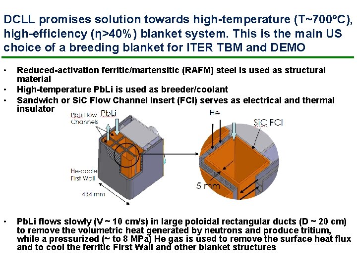
DCLL promises solution towards high-temperature (T~700 C), high-efficiency (η>40%) blanket system. This is the main US choice of a breeding blanket for ITER TBM and DEMO • • Reduced-activation ferritic/martensitic (RAFM) steel is used as structural material High-temperature Pb. Li is used as breeder/coolant Sandwich or Si. C Flow Channel Insert (FCI) serves as electrical and thermal insulator Pb. Li flows slowly (V ~ 10 cm/s) in large poloidal rectangular ducts (D ~ 20 cm) to remove the volumetric heat generated by neutrons and produce tritium, while a pressurized (~ to 8 MPa) He gas is used to remove the surface heat flux and to cool the ferritic First Wall and other blanket structures
This presentation overviews recent* R&D (mostly at UCLA) for DCLL in the area of MHD thermofluids: 1) 2) 3) 4) MHD and Heat Transfer - Instabilities, transitions and MHD turbulence - Mixed-convection flows - Pb. Li experiments Fluid materials interaction (RAFM/Pb. Li corrosion) Tritium transport FCI development and characterization - FCI development, fabrication and testing - FCI experiments and FCI flow modeling - Qualification of Si. C material * US ITER TBM 2004 -2011 and current US blanket studies
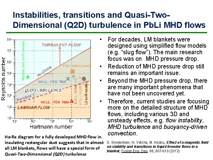
Instabilities, transitions and Quasi-Two. Dimensional (Q 2 D) turbulence in Pb. Li MHD flows • For decades, LM blankets were designed using simplified flow models (e. g. “slug flow”). The main research focus was on MHD pressure drop. • Reduction of MHD pressure drop still remains an important issue. • Beyond the MHD pressure drop, there are many important phenomena that have not been uncovered yet. • Therefore, current studies are focusing more on the detailed structure of MHD flows, including various 3 D and unsteady effects, e. g. flow instability, MHD turbulence and buoyancy-driven convection. Ha-Re diagram for a fully developed MHD flow in insulating rectangular duct suggests that in almost all LM blankets, flows will have a special form of Quasi-Two-Dimensional (Q 2 D) turbulence S. Smolentsev, N. Vetcha, M. Abdou, Effect of a magnetic field on stability and transitions in liquid breeder flows in a blanket, Fusion Eng. Des. 88, 607 -610 (2013).
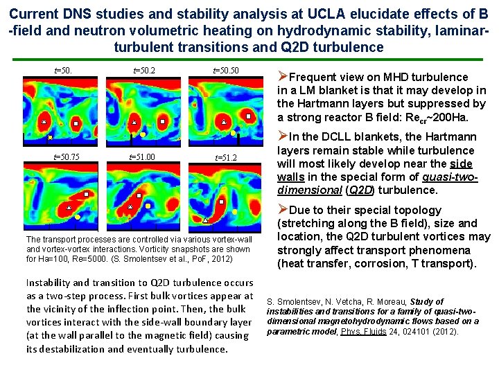
Current DNS studies and stability analysis at UCLA elucidate effects of B -field and neutron volumetric heating on hydrodynamic stability, laminarturbulent transitions and Q 2 D turbulence t=50. 0 t=50. 2 5 t=50. 50 ØFrequent view on MHD turbulence in a LM blanket is that it may develop in the Hartmann layers but suppressed by a strong reactor B field: Recr~200 Ha. ØIn the DCLL blankets, the Hartmann t=50. 75 t=51. 00 t=51. 2 5 layers remain stable while turbulence will most likely develop near the side walls in the special form of quasi-twodimensional (Q 2 D) turbulence. ØDue to their special topology The transport processes are controlled via various vortex-wall and vortex-vortex interactions. Vorticity snapshots are shown for Ha=100, Re=5000. (S. Smolentsev et al. , Po. F, 2012) Instability and transition to Q 2 D turbulence occurs as a two-step process. First bulk vortices appear at the vicinity of the inflection point. Then, the bulk vortices interact with the side-wall boundary layer (at the wall parallel to the magnetic field) causing its destabilization and eventually turbulence. (stretching along the B field), size and location, the Q 2 D turbulent vortices may strongly affect transport phenomena (heat transfer, corrosion, T transport). S. Smolentsev, N. Vetcha, R. Moreau, Study of instabilities and transitions for a family of quasi-twodimensional magnetohydrodynamic flows based on a parametric model, Phys. Fluids 24, 024101 (2012).
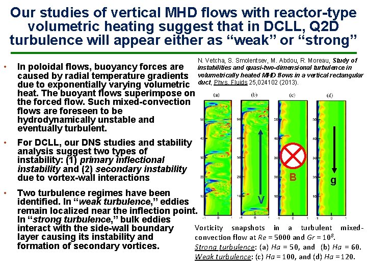
Our studies of vertical MHD flows with reactor-type volumetric heating suggest that in DCLL, Q 2 D turbulence will appear either as “weak” or “strong” • In poloidal flows, buoyancy forces are caused by radial temperature gradients due to exponentially varying volumetric heat. The buoyant flows superimpose on the forced flow. Such mixed-convection flows are foreseen to be hydrodynamically unstable and eventually turbulent. • For DCLL, our DNS studies and stability analysis suggest two types of instability: (1) primary inflectional instability and (2) secondary instability due to vortex-wall interactions • N. Vetcha, S. Smolentsev, M. Abdou, R. Moreau, Study of instabilities and quasi-two-dimensional turbulence in volumetrically heated MHD flows in a vertical rectangular duct, Phys. Fluids 25, 024102 (2013). B g Two turbulence regimes have been V identified. In “weak turbulence, ” eddies remain localized near the inflection point. In “strong turbulence, ” bulk eddies Vorticity snapshots in a turbulent mixedinteract with the side-wall boundary convection flow at Re = 5000 and Gr = 108. layer causing its instability and formation of secondary vortices. Strong turbulence: (a) Ha = 50, and (b) Ha = 60. Weak turbulence: (c) Ha = 100, and (d) Ha = 120.
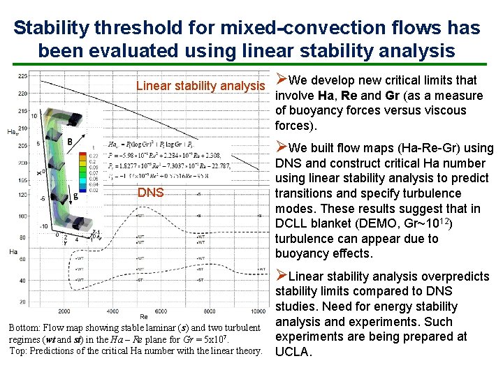
Stability threshold for mixed-convection flows has been evaluated using linear stability analysis Linear stability analysis ØWe develop new critical limits that involve Ha, Re and Gr (as a measure of buoyancy forces versus viscous forces). ØWe built flow maps (Ha-Re-Gr) using DNS and construct critical Ha number using linear stability analysis to predict transitions and specify turbulence modes. These results suggest that in DCLL blanket (DEMO, Gr~1012) turbulence can appear due to buoyancy effects. ØLinear stability analysis overpredicts Bottom: Flow map showing stable laminar (s) and two turbulent regimes (wt and st) in the Ha – Re plane for Gr = 5 x 10⁷. Top: Predictions of the critical Ha number with the linear theory. stability limits compared to DNS studies. Need for energy stability analysis and experiments. Such experiments are being prepared at UCLA.
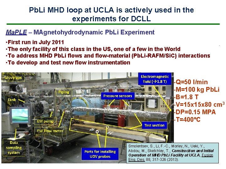
Pb. Li MHD loop at UCLA is actively used in the experiments for DCLL Ma. PLE – MAgnetohydrodynamic Pb. Li Experiment • First run in July 2011 • The only facility of this class in the US, one of a few in the World • To address MHD Pb. Li flows and flow-material (Pb. Li-RAFM/Si. C) interactions • To develop and test new flow instrumentation -Q=50 l/min -M=100 kg Pb. Li -B=1. 8 T -V=15 x 80 cm 3 -DP=0. 15 MPA -T=400 C Smolentsev, S. , Li, F. -C. , Morley, N. , Ueki, Y. , Abdou, M. , Sketchley, T. , Construction and Initial Operation of MHD Pb. Li Facility at UCLA, Fusion Eng. Des. 88, 317 -326 (2013).
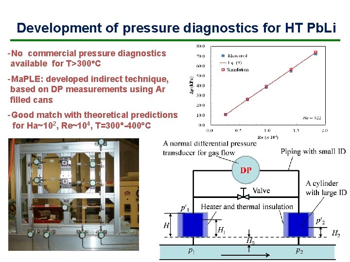
Development of pressure diagnostics for HT Pb. Li -No commercial pressure diagnostics available for T>300 C -Ma. PLE: developed indirect technique, based on DP measurements using Ar filled cans -Good match with theoretical predictions for Ha~102, Re~104, T=300 -400 C
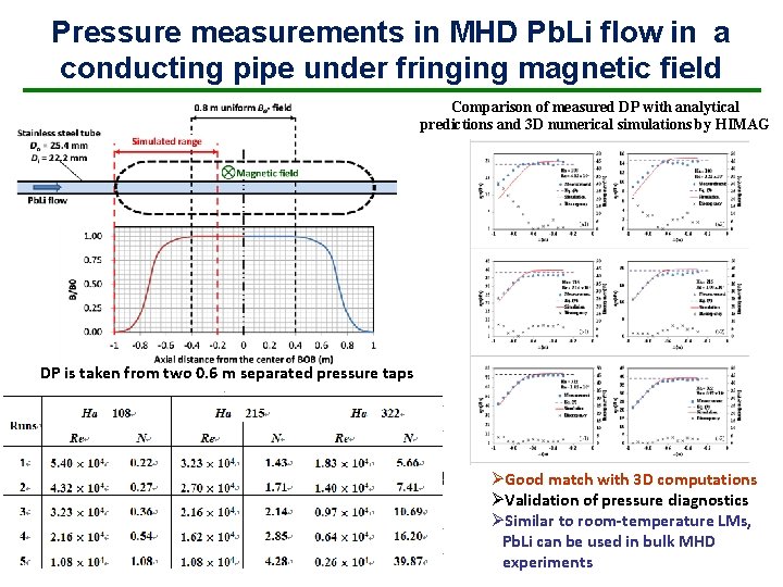
Pressure measurements in MHD Pb. Li flow in a conducting pipe under fringing magnetic field Comparison of measured DP with analytical predictions and 3 D numerical simulations by HIMAG DP is taken from two 0. 6 m separated pressure taps ØGood match with 3 D computations ØValidation of pressure diagnostics ØSimilar to room-temperature LMs, Pb. Li can be used in bulk MHD experiments
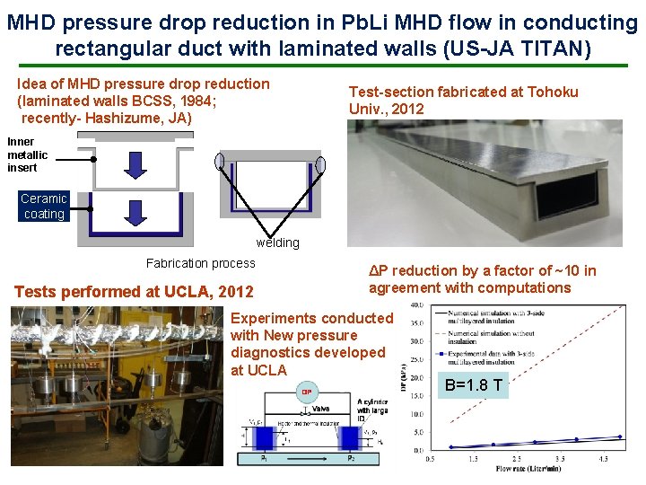
MHD pressure drop reduction in Pb. Li MHD flow in conducting rectangular duct with laminated walls (US-JA TITAN) Idea of MHD pressure drop reduction (laminated walls BCSS, 1984; recently- Hashizume, JA) Test-section fabricated at Tohoku Univ. , 2012 Inner metallic insert Ceramic coating welding Fabrication process Tests performed at UCLA, 2012 ΔP reduction by a factor of ~10 in agreement with computations Experiments conducted with New pressure diagnostics developed at UCLA B=1. 8 T
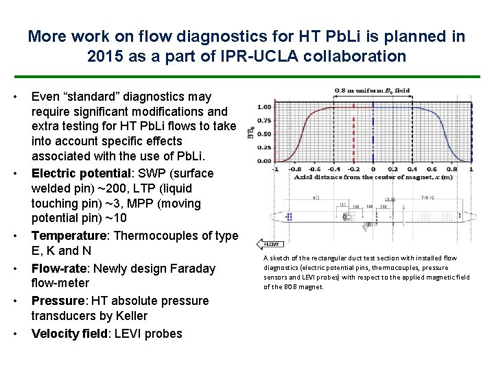
More work on flow diagnostics for HT Pb. Li is planned in 2015 as a part of IPR-UCLA collaboration • • • Even “standard” diagnostics may require significant modifications and extra testing for HT Pb. Li flows to take into account specific effects associated with the use of Pb. Li. Electric potential: SWP (surface welded pin) ~200, LTP (liquid touching pin) ~3, MPP (moving potential pin) ~10 Temperature: Thermocouples of type E, K and N Flow-rate: Newly design Faraday flow-meter Pressure: HT absolute pressure transducers by Keller Velocity field: LEVI probes A sketch of the rectangular duct test section with installed flow diagnostics (electric potential pins, thermocouples, pressure sensors and LEVI probes) with respect to the applied magnetic field of the BOB magnet.
Recent* R&D for DCLL in the area of: 1) 2) 3) 4) MHD and Heat Transfer - Instabilities, transitions and MHD turbulence - Mixed-convection flows - Pb. Li experiments Fluid materials interaction (RAFM/Pb. Li corrosion) Tritium transport FCI development and characterization - FCI development, fabrication and testing - FCI experiments and FCI flow modeling - Qualification of Si. C material * US ITER TBM 2004 -2011 and current US blanket studies
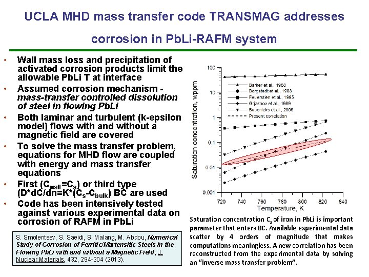
UCLA MHD mass transfer code TRANSMAG addresses corrosion in Pb. Li-RAFM system • • • Wall mass loss and precipitation of activated corrosion products limit the allowable Pb. Li T at interface Assumed corrosion mechanism mass-transfer controlled dissolution of steel in flowing Pb. Li Both laminar and turbulent (k-epsilon model) flows with and without a magnetic field are covered To solve the mass transfer problem, equations for MHD flow are coupled with energy and mass transfer equations First (Cwall=Cs) or third type (D*d. C/dn=K*(Cs-Cbulk) BC are used Code has been intensively tested against various experimental data on corrosion of RAFM in Pb. Li S. Smolentsev, S. Saeidi, S. Malang, M. Abdou, Numerical Study of Corrosion of Ferritic/Martensitic Steels in the Flowing Pb. Li with and without a Magnetic Field , J. Nuclear Materials, 432, 294 -304 (2013). Saturation concentration Cs of iron in Pb. Li is important parameter that enters BC. Available experimental data scatter by 4 orders of magnitude that makes computations meaningless. A new correlation has been reconstructed from the experimental data by solving an “inverse mass transfer problem”.
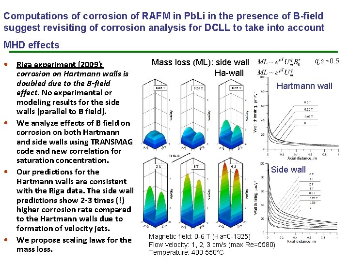
Computations of corrosion of RAFM in Pb. Li in the presence of B-field suggest revisiting of corrosion analysis for DCLL to take into account MHD effects • Riga experiment (2009): corrosion on Hartmann walls is doubled due to the B-field effect. No experimental or modeling results for the side walls (parallel to B field). • We analyze effects of B field on corrosion on both Hartmann and side walls using TRANSMAG code and new correlation for saturation concentration. • Our predictions for the Hartmann walls are consistent with the Riga data. The side wall predictions show 2 -3 times (!) higher corrosion rate compared to the Hartmann walls due to formation of velocity jets. • We propose scaling laws for the mass loss. q, s ~0. 5 Mass loss (ML): side wall Ha-wall Hartmann wall Side wall Magnetic field: 0 -6 T (Ha=0 -1325) Flow velocity: 1, 2, 3 cm/s (max Re=5580) Temperature: 400 -550 C
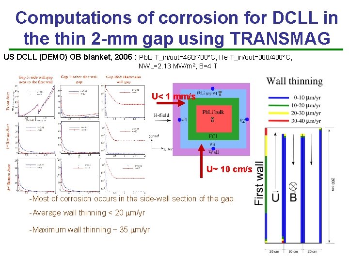
Computations of corrosion for DCLL in the thin 2 -mm gap using TRANSMAG US DCLL (DEMO) OB blanket, 2006 : Pb. Li T_in/out=460/700 C, He T_in/out=300/480 C, NWL=2. 13 MW/m 2, B=4 T U< 1 mm/s U~ 10 cm/s -Most of corrosion occurs in the side-wall section of the gap -Average wall thinning < 20 m/yr -Maximum wall thinning ~ 35 m/yr
Recent* R&D for DCLL in the area of: 1) 2) 3) 4) MHD and Heat Transfer - Instabilities, transitions and MHD turbulence - Mixed-convection flows - Pb. Li experiments Fluid materials interaction (RAFM/Pb. Li corrosion) Tritium transport FCI development and characterization - FCI development, fabrication and testing - FCI experiments and FCI flow modeling - Qualification of Si. C material * US ITER TBM 2004 -2011 and current US blanket studies
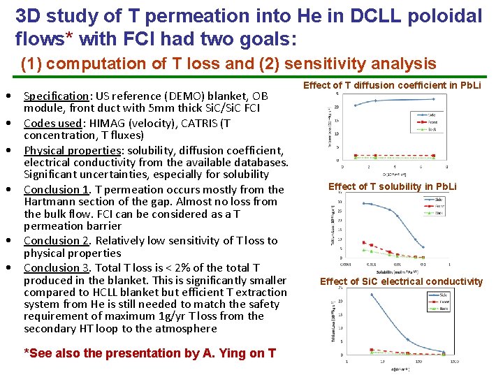
3 D study of T permeation into He in DCLL poloidal flows* with FCI had two goals: (1) computation of T loss and (2) sensitivity analysis • Specification: US reference (DEMO) blanket, OB module, front duct with 5 mm thick Si. C/Si. C FCI • Codes used: HIMAG (velocity), CATRIS (T concentration, T fluxes) • Physical properties: solubility, diffusion coefficient, electrical conductivity from the available databases. Significant uncertainties, especially for solubility • Conclusion 1. T permeation occurs mostly from the Hartmann section of the gap. Almost no loss from the bulk flow. FCI can be considered as a T permeation barrier • Conclusion 2. Relatively low sensitivity of T loss to physical properties • Conclusion 3. Total T loss is < 2% of the total T produced in the blanket. This is significantly smaller compared to HCLL blanket but efficient T extraction system from He is still needed to match the safety requirement of maximum 1 g/yr T loss from the secondary HT loop to the atmosphere *See also the presentation by A. Ying on T Effect of T diffusion coefficient in Pb. Li Effect of T solubility in Pb. Li Effect of Si. C electrical conductivity
Recent* R&D for DCLL in the area of: 1) 2) 3) 4) MHD and Heat Transfer - Instabilities, transitions and MHD turbulence - Mixed-convection flows - Pb. Li experiments Fluid materials interaction (RAFM/Pb. Li corrosion) Tritium transport FCI development, characterization - FCI development, fabrication and testing - FCI experiments and FCI flow modeling - Qualification of Si. C material * US ITER TBM 2004 -2011 and current US blanket studies
Requirements on FCI and FCI material • Low electrical conductivity to keep the MHD pressure drop in the module < 2 MPa • Low thermal conductivity to provide Pb. Li-RAFM interface temperature <470 C and minimize heat losses into He • Compatibility with Pb. Li at elevated temperatures more than 700 C • Retaining physical integrity and desirable properties during operation under long-time exposure to neutron irradiation and temperature gradients • No cracking, no significant Pb. Li ingress to avoid degradation of insulating properties
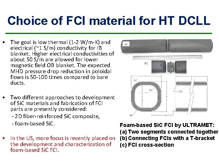
Choice of FCI material for HT DCLL • The goal is low thermal (1 -2 W/m-K) and electrical (~1 S/m) conductivity for IB blanket. Higher electrical conductivities of about 50 S/m are allowed for lower magnetic field OB blanket. The expected MHD pressure drop reduction in poloidal flows is 50 -100 times compared to bare ducts. • Two different approaches to development of Si. C materials and fabrication of FCI parts are presently considered: - 2 D fiber-reinforced Si. C composite, - foam-based Si. C. Foam-based Si. C FCI by ULTRAMET: (a) Two segments connected together • In the US, more focus is recently placed on (b) Connecting FCIs with a T-bracket the development and characterization of (c) FCI cross-section foam-based Si. C FCI.
UCLA has performed several tests of foam-based Si. C FCI samples by Ultramet in static and flowing Pb. Li conditions • FCI samples filled with Silica or Carbon aerogel: 8 cm x 8 cm, L=12, 30 cm, tw=1 cm. Some samples are CVD coated. • Static HT chamber with internal heating and external air cooling: P~0. 1, 0. 5, 1. 0 MPa, T= 700 C, 75 K/cm, 100 hrs. • Dynamic testing in Ma. PLE: 300 C, Pmax=0. 1 Mpa, Umax~10 cm/s, ~ 10 months. • In some cases Pb. Li ingress was observed. In particular, it was observed in dynamic testing. This may indicate to some fabrication issues. • Brian Williams (Ultramet): “My conclusion was that if the aerogel is dense enough, it can prevent metal ingress but more optimization of the aerogel density is needed. ” Static tests Dynamic tests A Si. C sample before and after testing in static Pb. Li at 700 C, 100 hrs, and 1 MPa