PL 7 003 Years of experience in ENEA
- Slides: 35
PL 7 – 003 Years of experience in ENEA Frascati Accelerator LAB Paolo Nenzi on behalf of ENEA Frascati Team Acc. Sys Pleasanton (CA), USA 11 December 2014
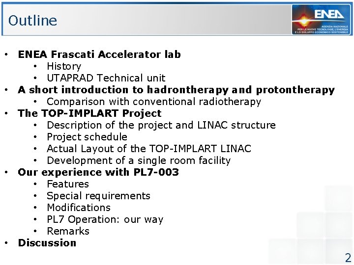
Outline • ENEA Frascati Accelerator lab • History • UTAPRAD Technical unit • A short introduction to hadrontherapy and protontherapy • Comparison with conventional radiotherapy • The TOP-IMPLART Project • Description of the project and LINAC structure • Project schedule • Actual Layout of the TOP-IMPLART LINAC • Development of a single room facility • Our experience with PL 7 -003 • Features • Special requirements • Modifications • PL 7 Operation: our way • Remarks • Discussion 2
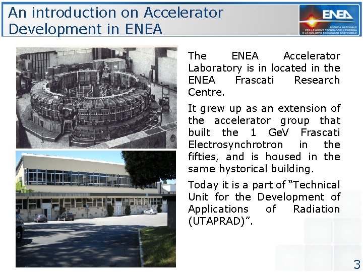
An introduction on Accelerator Development in ENEA The ENEA Accelerator Laboratory is in located in the ENEA Frascati Research Centre. It grew up as an extension of the accelerator group that built the 1 Ge. V Frascati Electrosynchrotron in the fifties, and is housed in the same hystorical building. Today it is a part of “Technical Unit for the Development of Applications of Radiation (UTAPRAD)”. 3
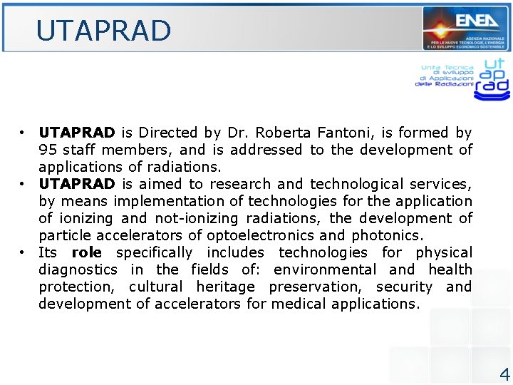
UTAPRAD • UTAPRAD is Directed by Dr. Roberta Fantoni, is formed by 95 staff members, and is addressed to the development of applications of radiations. • UTAPRAD is aimed to research and technological services, by means implementation of technologies for the application of ionizing and not-ionizing radiations, the development of particle accelerators of optoelectronics and photonics. • Its role specifically includes technologies for physical diagnostics in the fields of: environmental and health protection, cultural heritage preservation, security and development of accelerators for medical applications. 4
Very short introduction to HADRONTHERAPY AND PROTONTHERAPY 5
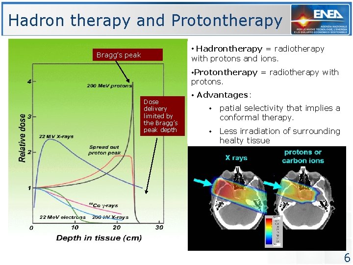
Hadron therapy and Protontherapy • Hadrontherapy = radiotherapy Bragg’s peak with protons and ions. • Protontherapy = radiotherapy with protons. Dose delivery limited by the Bragg’s peak depth • Advantages: • patial selectivity that implies a conformal therapy. • Less irradiation of surrounding healty tissue 6
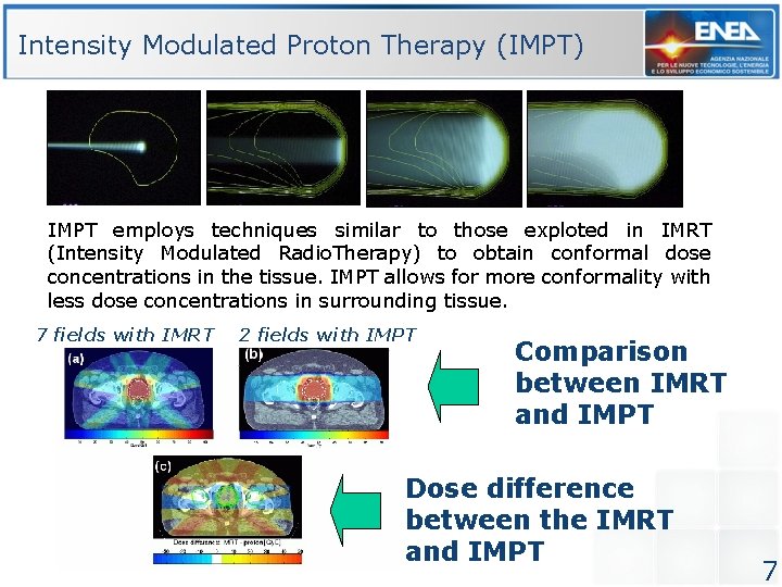
Intensity Modulated Proton Therapy (IMPT) IMPT employs techniques similar to those exploted in IMRT (Intensity Modulated Radio. Therapy) to obtain conformal dose concentrations in the tissue. IMPT allows for more conformality with less dose concentrations in surrounding tissue. 7 fields with IMRT 2 fields with IMPT Comparison between IMRT and IMPT Dose difference between the IMRT and IMPT 7
Description of THE TOP-IMPLART PROJECT 8
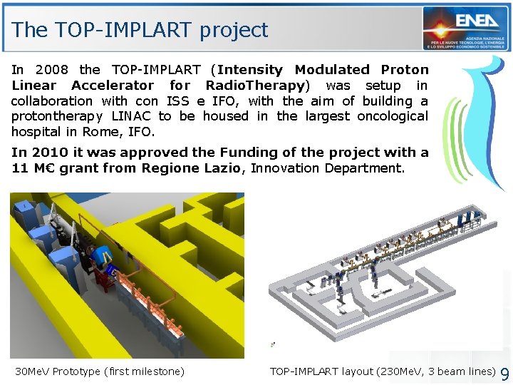
The TOP-IMPLART project In 2008 the TOP-IMPLART (Intensity Modulated Proton Linear Accelerator for Radio. Therapy) was setup in collaboration with con ISS e IFO, with the aim of building a protontherapy LINAC to be housed in the largest oncological hospital in Rome, IFO. In 2010 it was approved the Funding of the project with a 11 M€ grant from Regione Lazio, Innovation Department. 30 Me. V Prototype (first milestone) TOP-IMPLART layout (230 Me. V, 3 beam lines) 9
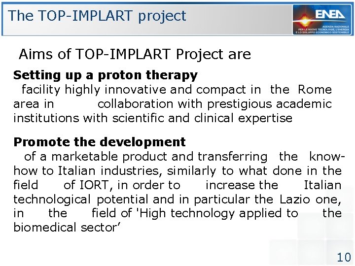
The TOP-IMPLART project Aims of TOP-IMPLART Project are Setting up a proton therapy facility highly innovative and compact in the Rome area in collaboration with prestigious academic institutions with scientific and clinical expertise Promote the development of a marketable product and transferring the knowhow to Italian industries, similarly to what done in the field of IORT, in order to increase the Italian technological potential and in particular the Lazio one, in the field of 'High technology applied to the biomedical sector’ 10
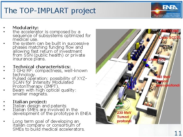
The TOP-IMPLART project • • • Modularity: the accelerator is composed by a sequence of subsystems optimized for medical use. the system can be built in successive phases matching funding flow and allowing fast return of investment from SSN (public health) or private insurance plans. Technical characteristics: 3 GHz RF: compactness, well-known technology. Pulsed operation: possibility of XYZSCAN for Intensity Modulated Proton. Therapy (IMPT). Beam with high optical quality: smaller magnets. Italian project: Italian design and patents Italian SMEs are involved in the development of the prototype in ENEA . Long term goal of developing an italian company or consortium of SMEs to build medical accelerators. 11
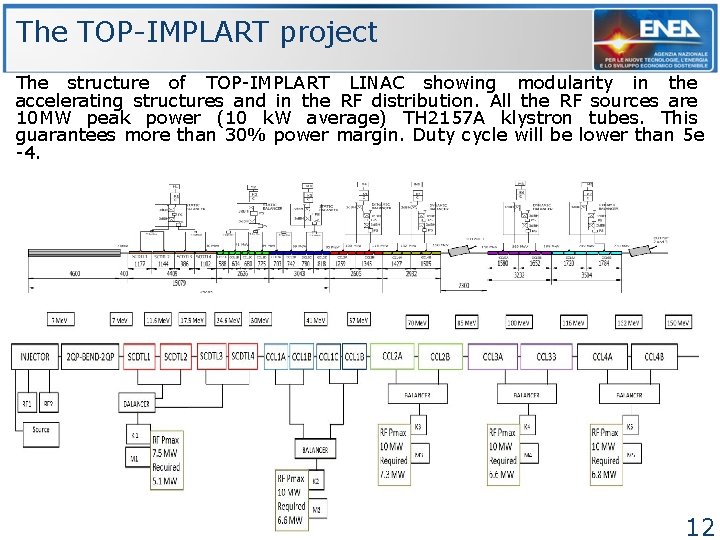
The TOP-IMPLART project The structure of TOP-IMPLART LINAC showing modularity in the accelerating structures and in the RF distribution. All the RF sources are 10 MW peak power (10 k. W average) TH 2157 A klystron tubes. This guarantees more than 30% power margin. Duty cycle will be lower than 5 e -4. 12 12
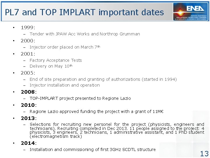
PL 7 and TOP IMPLART important dates • 1999: – • 2000: – • Ragione Lazio approved funding the project with a grant of 11 M€ 2013: – • TOP-IMPLART project presented to Regione Lazio 2010: – • End of site preparation and granting of authorizations (started in 1994) Injector installation and operation 2008: – • Factory Acceptance Tests Delivery on May 10 th 2005: – – • Injector order placed on March 7 th 2001: – – • Tender with JPAW Acc Works and Northrop Grumman Selections for recruiting new personel for the project (physicists, engineers and technicians). Recruiting completed in Dec 2013. 11 people assigned to the project: 4 physicists, 3 engineers, 2 technicians, 1 administrative assistant, and 1 Ph. D student (electromagnetism track) 2014: – Installation and commissioning of first 3 GHz SCDTL structure 13
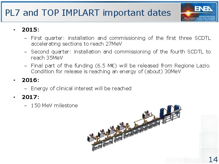
PL 7 and TOP IMPLART important dates • 2015: – First quarter: installation and commissioning of the first three SCDTL accelerating sections to reach 27 Me. V – Second quarter: installation and commissioning of the fourth SCDTL to reach 35 Me. V – Final part of the funding (6. 5 M€) will be released from Regione Lazio. Condition for release is reaching an energy of (about) 30 Me. V • 2016: – Energy of clinical interest will be reached • 2017: – 150 Me. V milestone 14
Description of the ACTUAL LAYOUT OF TOP-IMPLART LINAC 15
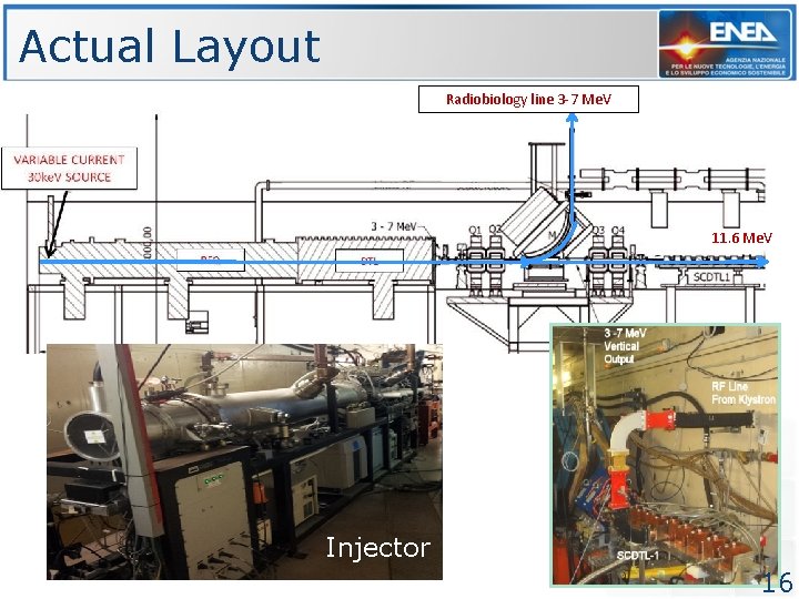
Actual Layout Radiobiology line 3 -7 Me. V 11. 6 Me. V Injector 16
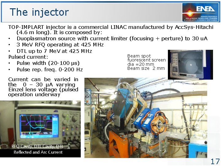
The injector TOP-IMPLART injector is a commercial LINAC manufactured by Acc. Sys-Hitachi (4. 6 m long). It is composed by: • Duoplasmatron source with current limiter (focusing + perture) to 30 u. A • 3 Me. V RFQ operating at 425 MHz • DTL up to 7 Me. V at 425 MHz Beam spot Pulsed current: fuorescent screen • Pulse width (20 -100 μs) dia =20 mm Beam size 2 mm • Pulse rep. freq. 0 -200 Hz Current can be varied in the 0 – 30 μA varying Einzel lens voltage (pulsed operation underway 17
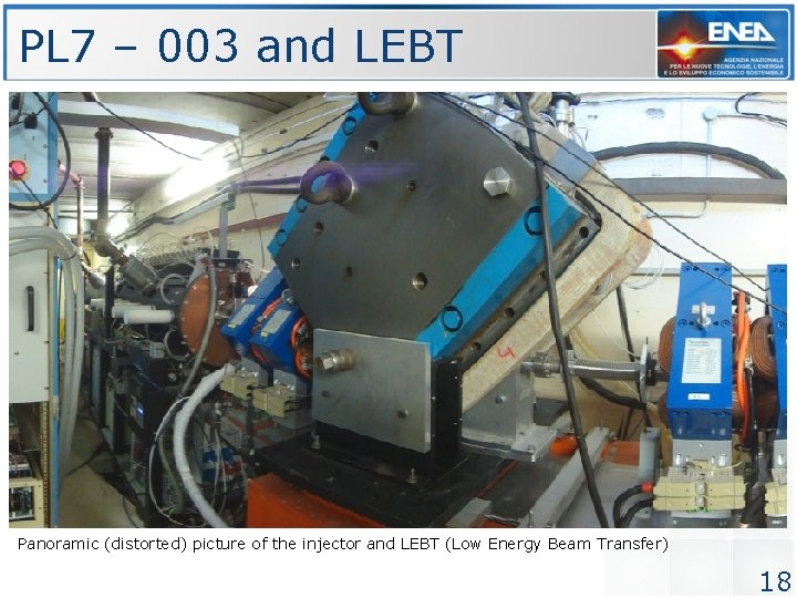
PL 7 – 003 and LEBT Panoramic (distorted) picture of the injector and LEBT (Low Energy Beam Transfer) 18
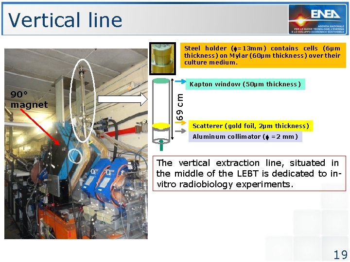
Vertical line Steel holder ( =13 mm) contains cells (6µm thickness) on Mylar (60µm thickness) over their culture medium. 90° magnet 69 cm Kapton window (50µm thickness) Scatterer (gold foil, 2µm thickness) Aluminum collimator ( =2 mm) The vertical extraction line, situated in the middle of the LEBT is dedicated to invitro radiobiology experiments. 19
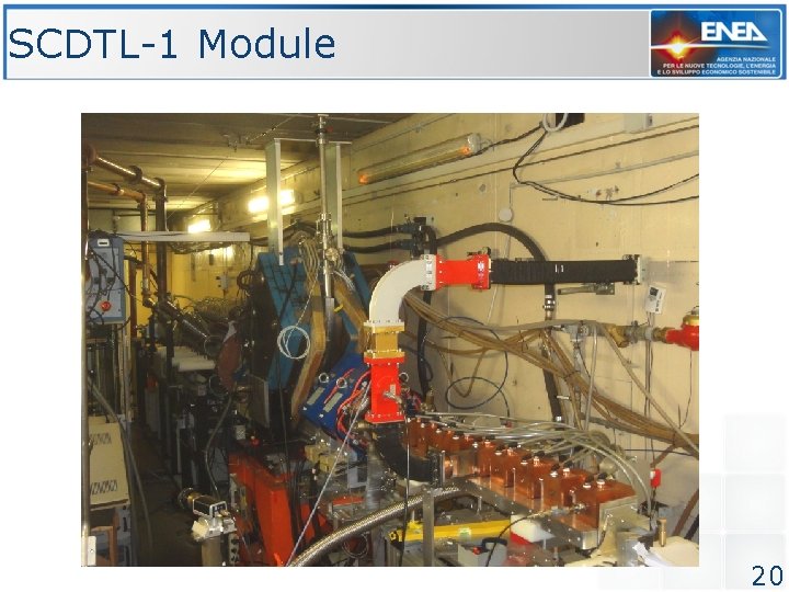
SCDTL-1 Module 20
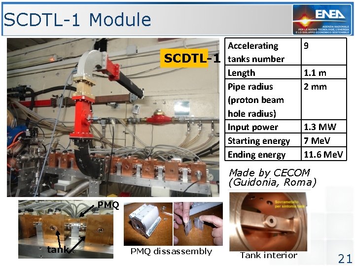
SCDTL-1 Module SCDTL-1 Accelerating tanks number Length Pipe radius (proton beam hole radius) Input power Starting energy Ending energy 9 1. 1 m 2 mm 1. 3 MW 7 Me. V 11. 6 Me. V Made by CECOM (Guidonia, Roma) PMQ tank PMQ dissassembly Tank interior 21
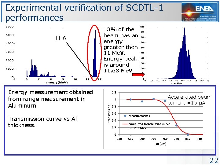
Experimental verification of SCDTL-1 performances 11. 6 Energy measurement obtained from range measurement in Aluminum. 43% of the beam has an energy greater then 11 Me. V. Energy peak is around 11. 63 Me. V Accelerated beam current =15 µA Transmission curve vs Al thickness. 22
New development: TOP-IMPLART SINGLE ROOM FACILITY 23
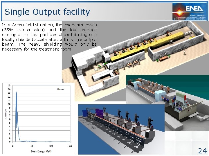
Single Output facility In a Green field situation, the low beam losses (35% transmission) and the low average energy of the lost particles allow thinking of a locally shielded accelerator, with single output beam, The heavy shielding would only be necessary for the treatment room 24
Our experience with PL 7 - 003 25
Features of PL 7 -003 • Proton source: – Duoplasmatron Source 30 ke. V • Acceleration – RFQ 3 Me. V – DTL 4 Me. V • Control Software: – LINCON 1. 1 written by Marianne Hamm on Labview 6. 1, running on Windows 98 – Lab. View source available – We have an updated version of the software running on a newer PC. – We tested the new combination but we never used it because of many controls are unconsinstent to settings – Alternative to optical control boards ? (Group 3 are obsolete) 26
Special requirements for our PL 7 -003 • Pulse Current: – Availability of Low and High current for different applications: • Radioisotope production : 8 m. A per pulse • Protontherapy linac injector: 100 -10 -1 μA per pulse – Retractable (1 mm dia) copper aperture at RFQ input • Pulsed Einzel Lens current to modulate output current: – Hard tube pulser designed by George Engemann(? ) never worked • Reduced DTL pulse: – 3 GHz LINAC works with a 4μs pulse – Need for a DTL pulse of up to 7 us 27
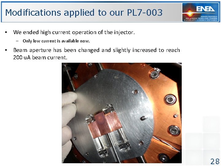
Modifications applied to our PL 7 -003 • We ended high current operation of the injector. – Only low current is available now. • Beam aperture has been changed and slightly increased to reach 200 u. A beam current. 28
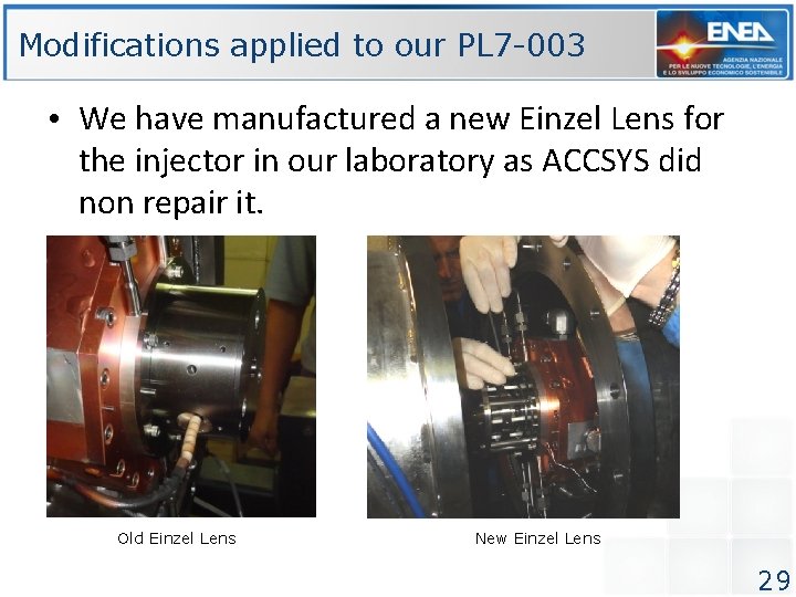
Modifications applied to our PL 7 -003 • We have manufactured a new Einzel Lens for the injector in our laboratory as ACCSYS did non repair it. Old Einzel Lens New Einzel Lens 29
Planned or undwerway Modifications to our PL 7 -003 • The following modifications have been planned to give better control to injector current and eventually suppress it for one or more pulse. • Current control is important for medical applications. • We have commissioned to a SME company an High Voltage pulsed source for the Einzel: – The pulser has been delivered to our facility and is currently under HV test. • An external enabling arc discharge is in development. • We are evaluating the possibility of inserting a chopper (10 k. V, 4 cm) in front of the Einzel lens. – Hints ? • (? ) Negative pulse on Pierce electrode (? ) • We would like to set and read injector variables from our control system (Lab. View 2014) to integrate it into the higher level control system. – How we can do this ? 30
PL 7 -003 operation: Our Way • We always operate PL 7 -003 at low current (200 u. A) with external trigger using a PRF in the 10 – 50 Hz range • Cavity fields: – RFQ Cavity field 4 -4. 25 (Standard 4. 11) – DTL Cavity Field 4. 7 – 5. 35 (standard 5. 2 – 5. 34) • Remark: it is impossible, of course, to make reflected power vanish both in RFQ and DTL – We asked Accsys several times to adjust coupling coefficient by loop rotation, without uccess. – Never mind, we can still operate this way: we can loose some power. 31
Remarks • We found that the PL 7 machine has been well done. – Electronics systems are well explained in the schematics (This is very important for such kind of machines). – We experienced some complexity and redundancy in controls and interlocks that sometimes seems to cause strange faults • The old control systems (LINCON 1. 1) it is functional and well designed. – The drawback is that is not possible to interface it with an higher level control system – We need an open system. • Arc is not properly stable for very accurate and stable operation at low currents – How we can improve arc stability at low currents ? • Feedback loops are hard to adjust: – There is no written explanation of procedure, – Potentiometers on the boards have no clear mark of their function • Sometimes at high rep rate DF yellow light prevents operation – We could not trace back to the cause • We need for an electronic maintenance training course 32
Thank you for attention! Coming to the END 33
Merry Christmas and happy 2015 … from TOP-IMPLART teame 34
Discussion Some point for discussion 1. 2. 3. 4. differences between actual machines and the one we have. Understanding the AM loop and how to tune it Tube testing system Latest developments on the control software: latest release, controller boards, source availability 5. Ask John Sexton about a possible visit to us 6. Request for offer for a maintenance course for the PL 7 7. Are you using FPGA boards on newer machines ? 8. Have you a working Einzel Lens pulsed source ? We have a design from George Engemann but we do not know if it works and how to operate it 9. New development in duoplasmatron source 10. Visit to factory 35