Performance issues on wireless networks CS 439 539

- Slides: 57
Performance issues on wireless networks CS 439 & 539 Prof. Maria Papadopouli University of Crete ICS-FORTH http: //www. ics. forth. gr/mobile 1
Wireless network topologies can be controlled by • Data rate • Channel allocation: different devices communicate at different channels In some cases, there is a channel dedicated for the control (management) and message exchange • • • Transmission power (power control) Carrier sense threshold Directional antennas Cognitive intelligent radios & software defined radios Node placement Different network architectures/deployments (e. g. , mesh networks, infrastructure-based, ad hoc) 2
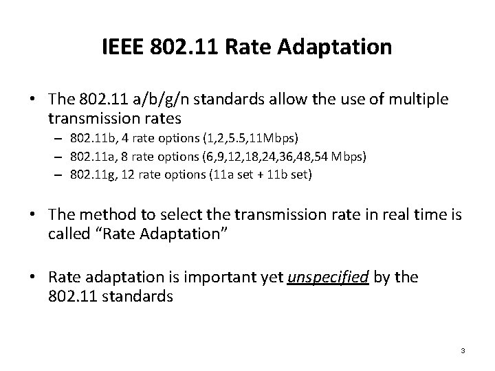
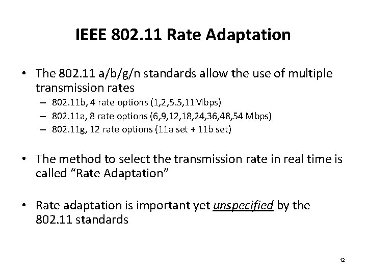
IEEE 802. 11 Rate Adaptation • The 802. 11 a/b/g/n standards allow the use of multiple transmission rates – 802. 11 b, 4 rate options (1, 2, 5. 5, 11 Mbps) – 802. 11 a, 8 rate options (6, 9, 12, 18, 24, 36, 48, 54 Mbps) – 802. 11 g, 12 rate options (11 a set + 11 b set) • The method to select the transmission rate in real time is called “Rate Adaptation” • Rate adaptation is important yet unspecified by the 802. 11 standards 3
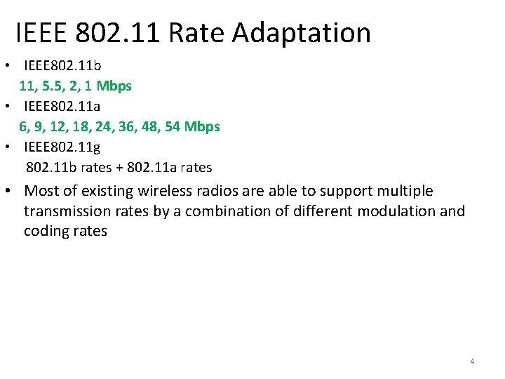
IEEE 802. 11 Rate Adaptation • IEEE 802. 11 b 11, 5. 5, 2, 1 Mbps • IEEE 802. 11 a 6, 9, 12, 18, 24, 36, 48, 54 Mbps • IEEE 802. 11 g 802. 11 b rates + 802. 11 a rates • Most of existing wireless radios are able to support multiple transmission rates by a combination of different modulation and coding rates 4
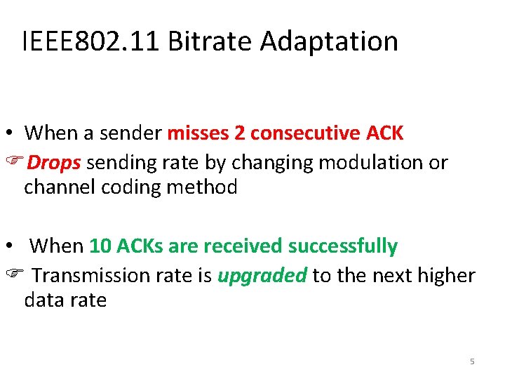
IEEE 802. 11 Bitrate Adaptation • When a sender misses 2 consecutive ACK Drops sending rate by changing modulation or channel coding method • When 10 ACKs are received successfully Transmission rate is upgraded to the next higher data rate 5
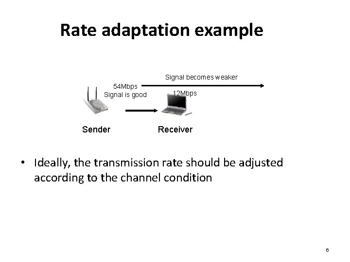
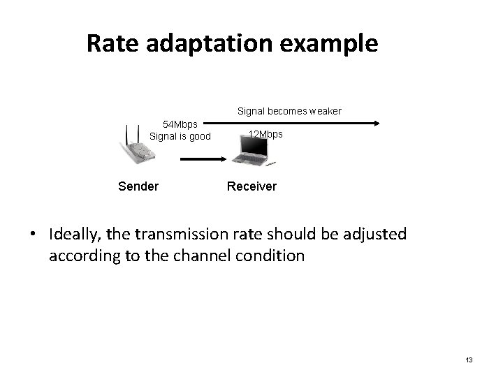
Rate adaptation example Signal becomes weaker 54 Mbps Signal is good Sender 12 Mbps Receiver • Ideally, the transmission rate should be adjusted according to the channel condition 6
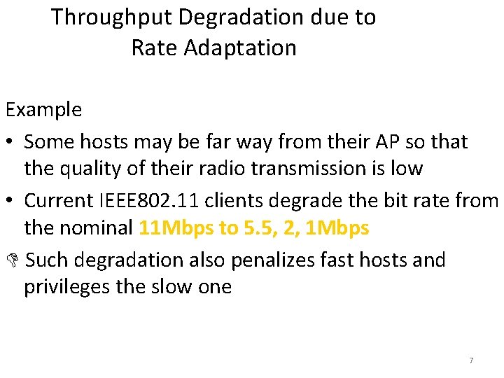
Throughput Degradation due to Rate Adaptation Example • Some hosts may be far way from their AP so that the quality of their radio transmission is low • Current IEEE 802. 11 clients degrade the bit rate from the nominal 11 Mbps to 5. 5, 2, 1 Mbps Such degradation also penalizes fast hosts and privileges the slow one 7
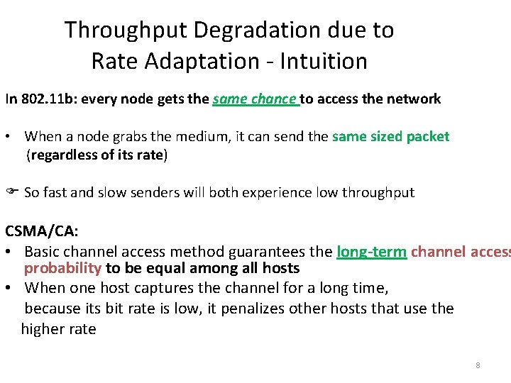
Throughput Degradation due to Rate Adaptation - Intuition In 802. 11 b: every node gets the same chance to access the network • When a node grabs the medium, it can send the same sized packet (regardless of its rate) So fast and slow senders will both experience low throughput CSMA/CA: • Basic channel access method guarantees the long-term channel access probability to be equal among all hosts • When one host captures the channel for a long time, because its bit rate is low, it penalizes other hosts that use the higher rate 8
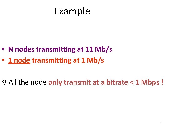
Example • N nodes transmitting at 11 Mb/s • 1 node transmitting at 1 Mb/s All the node only transmit at a bitrate < 1 Mbps ! 9
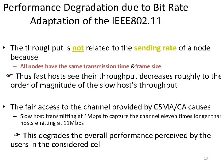
Performance Degradation due to Bit Rate Adaptation of the IEEE 802. 11 • The throughput is not related to the sending rate of a node because – All nodes have the same transmission time &frame size Thus fast hosts see their throughput decreases roughly to the order of magnitude of the slow host’s throughput • The fair access to the channel provided by CSMA/CA causes – Slow host transmitting at 1 Mbps to capture the channel eleven times longer than hosts emitting at 11 Mbps This degrades the overall performance perceived by the users in the considered cell 10
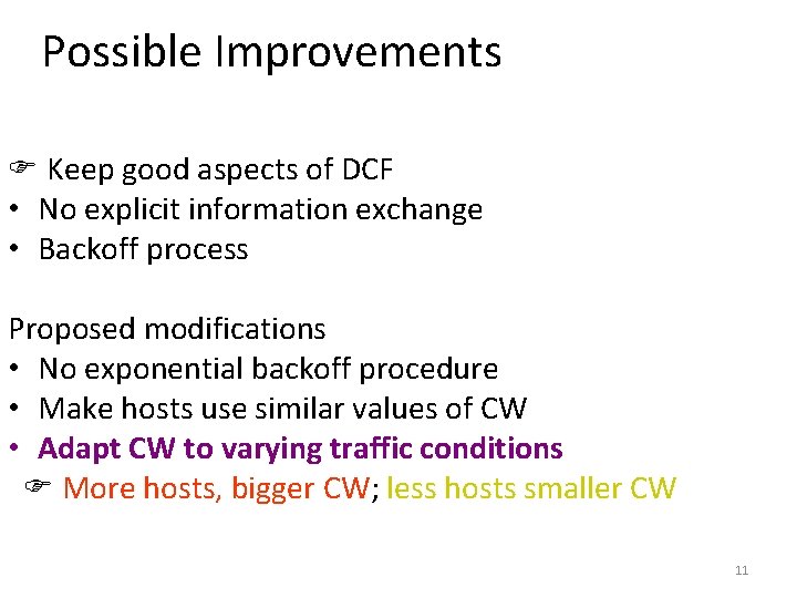
Possible Improvements Keep good aspects of DCF • No explicit information exchange • Backoff process Proposed modifications • No exponential backoff procedure • Make hosts use similar values of CW • Adapt CW to varying traffic conditions More hosts, bigger CW; less hosts smaller CW 11
IEEE 802. 11 Rate Adaptation • The 802. 11 a/b/g/n standards allow the use of multiple transmission rates – 802. 11 b, 4 rate options (1, 2, 5. 5, 11 Mbps) – 802. 11 a, 8 rate options (6, 9, 12, 18, 24, 36, 48, 54 Mbps) – 802. 11 g, 12 rate options (11 a set + 11 b set) • The method to select the transmission rate in real time is called “Rate Adaptation” • Rate adaptation is important yet unspecified by the 802. 11 standards 12
Rate adaptation example Signal becomes weaker 54 Mbps Signal is good Sender 12 Mbps Receiver • Ideally, the transmission rate should be adjusted according to the channel condition 13
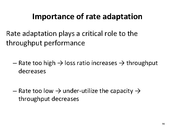
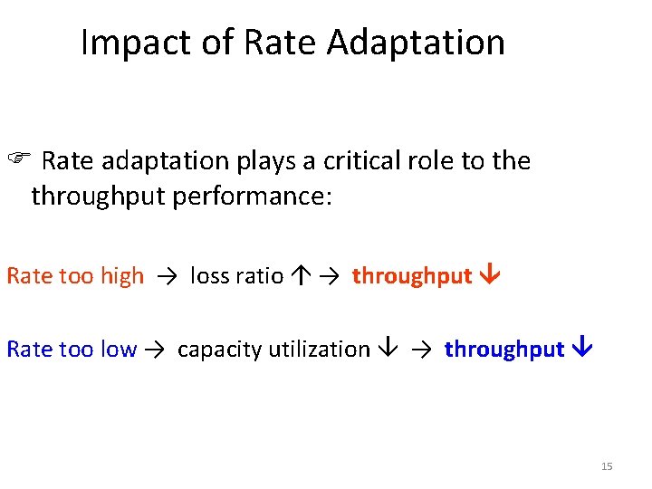
Importance of rate adaptation Rate adaptation plays a critical role to the throughput performance – Rate too high → loss ratio increases → throughput decreases – Rate too low → under-utilize the capacity → throughput decreases 14
Impact of Rate Adaptation Rate adaptation plays a critical role to the throughput performance: Rate too high → loss ratio → throughput Rate too low → capacity utilization → throughput 15
Client AP selection • Select the appropriate AP based on various criteria to optimize the service For that the client needs to • Perform probing/measurements to estimate various criteria
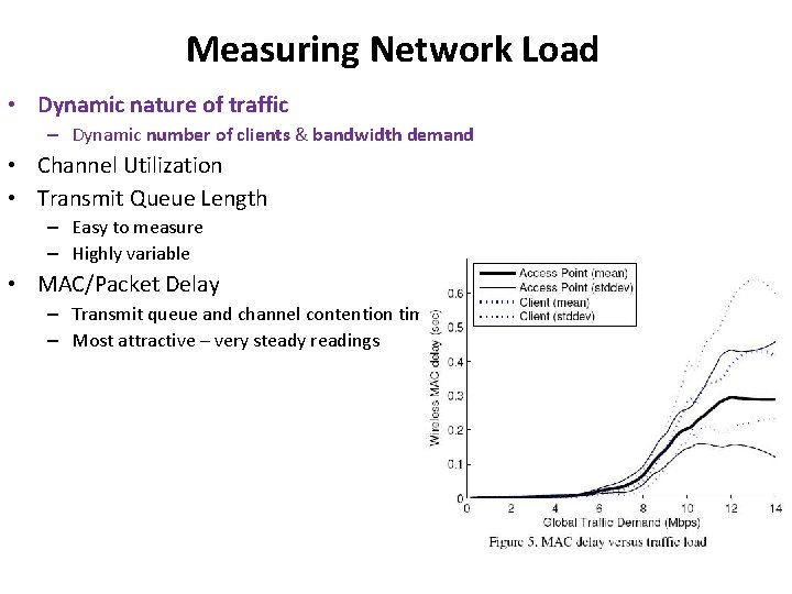
Measuring Network Load • Dynamic nature of traffic – Dynamic number of clients & bandwidth demand • Channel Utilization • Transmit Queue Length – Easy to measure – Highly variable • MAC/Packet Delay – Transmit queue and channel contention time measured – Most attractive – very steady readings
Measuring network load – tuning parameters • Load average Calculated using a moving average to negate small changes • Shrinking the averaging interval – Causes the system to converge on the maximum global throughput quickly – excessive channel switching • Increasing the averaging interval – Slower convergence – Less time wasted switching channels
Heterogeneous wireless networks • Crowded ISM band e. g. , coexistence of wireless LANs and wireless sensor networks
IEEE 802. 15. 4 wireless sensor network coexisting with an IEEE 802. 11 WLAN • The transmission power of WLAN terminals is orders of magnitude higher than that of co-existing WSN • The WLAN terminals are “blind” towards WSN transmissions: lower power, narrow band • WLAN causes harmful interference in the WSN, while itself remains unaffected from the WSN interferers • WSN nodes can avoid WLAN interference, and thus, costly packet retransmissions, only if they are armed with cognitive capabilities i. e. , optimize their transmission parameters and communication protocols accordingly • In the case of WLAN interferers, the sensors force the WLAN to backoff by sending short, high power jamming signals
Wireless channel exhibits rich channel dynamics in practical scenarios – Random channel error – Mobility-induced change – Collisions induced by • Hidden-terminals • Multiple contending clients 21
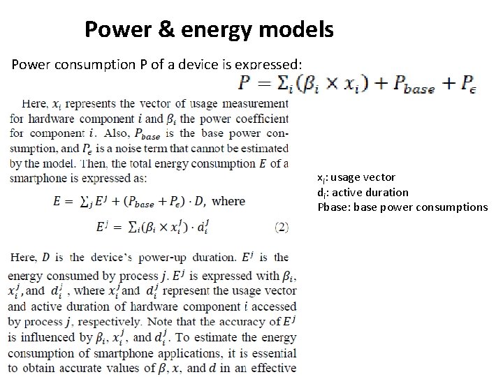
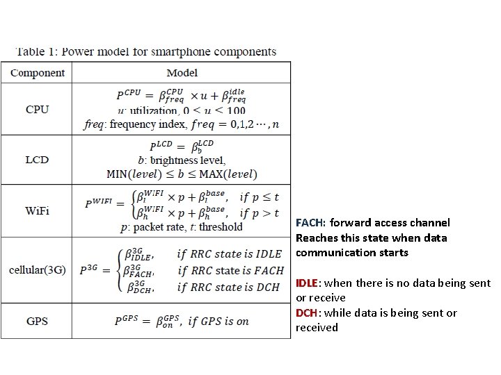
Power & energy models Power consumption P of a device is expressed: xi: usage vector di: active duration Pbase: base power consumptions
FACH: forward access channel Reaches this state when data communication starts IDLE: when there is no data being sent or receive DCH: while data is being sent or received
A discussion on Energy Management with IEEE 802. 11 n Reference: Snooze: Energy Management in 802. 11 n WLANs by Ki-Young Jang, Shuai Hao, Anmol Sheth, Ramesh Govindan
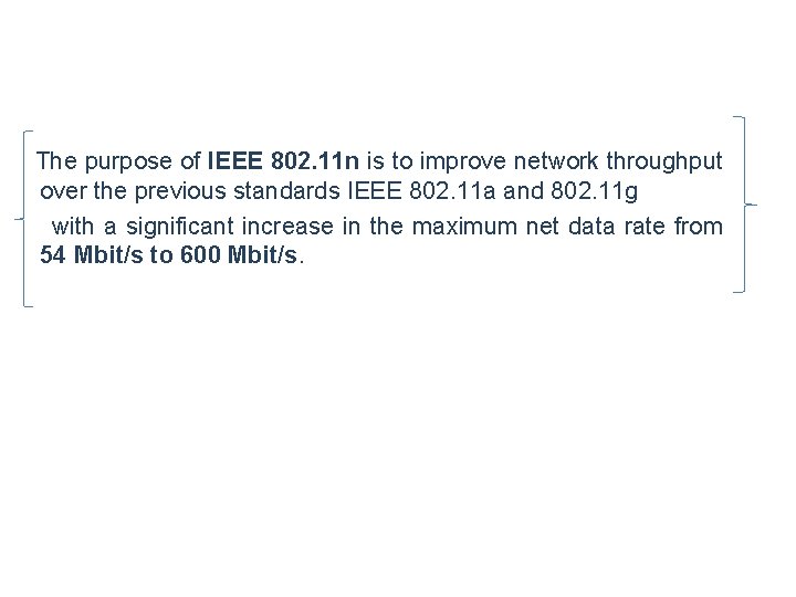
The purpose of IEEE 802. 11 n is to improve network throughput over the previous standards IEEE 802. 11 a and 802. 11 g with a significant increase in the maximum net data rate from 54 Mbit/s to 600 Mbit/s.
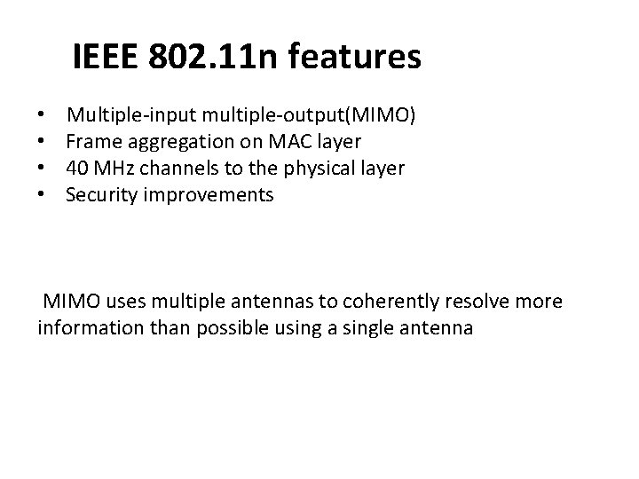
IEEE 802. 11 n features • • Multiple-input multiple-output(MIMO) Frame aggregation on MAC layer 40 MHz channels to the physical layer Security improvements MIMO uses multiple antennas to coherently resolve more information than possible using a single antenna
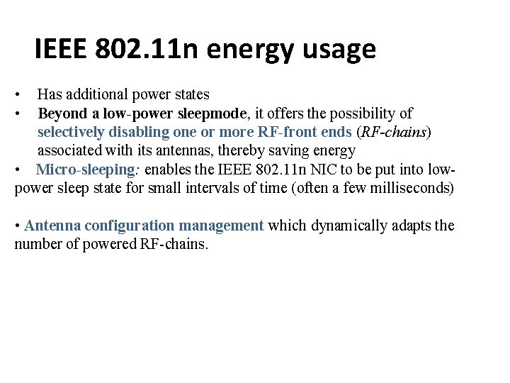
IEEE 802. 11 n energy usage • • Has additional power states Beyond a low-power sleepmode, it offers the possibility of selectively disabling one or more RF-front ends (RF-chains) associated with its antennas, thereby saving energy • Micro-sleeping: enables the IEEE 802. 11 n NIC to be put into lowpower sleep state for small intervals of time (often a few milliseconds) • Antenna configuration management which dynamically adapts the number of powered RF-chains.
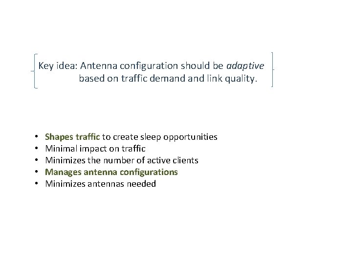
Key idea: Antenna configuration should be adaptive based on traffic demand link quality. • • • Shapes traffic to create sleep opportunities Minimal impact on traffic Minimizes the number of active clients Manages antenna configurations Minimizes antennas needed
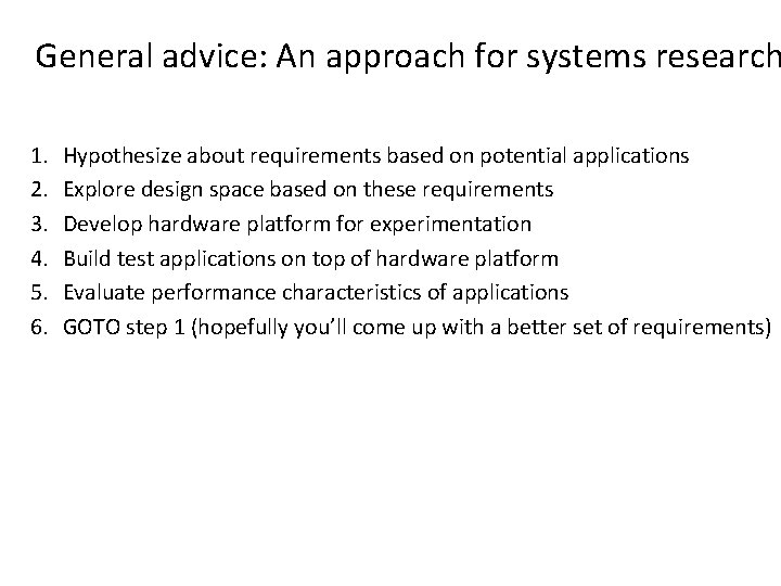
General advice: An approach for systems research 1. 2. 3. 4. 5. 6. Hypothesize about requirements based on potential applications Explore design space based on these requirements Develop hardware platform for experimentation Build test applications on top of hardware platform Evaluate performance characteristics of applications GOTO step 1 (hopefully you’ll come up with a better set of requirements)
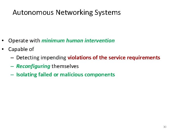
Autonomous Networking Systems • Operate with minimum human intervention • Capable of – Detecting impending violations of the service requirements – Reconfiguring themselves – Isolating failed or malicious components 30
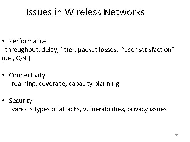
Issues in Wireless Networks • Performance throughput, delay, jitter, packet losses, “user satisfaction” (i. e. , Qo. E) • Connectivity roaming, coverage, capacity planning • Security various types of attacks, vulnerabilities, privacy issues 31
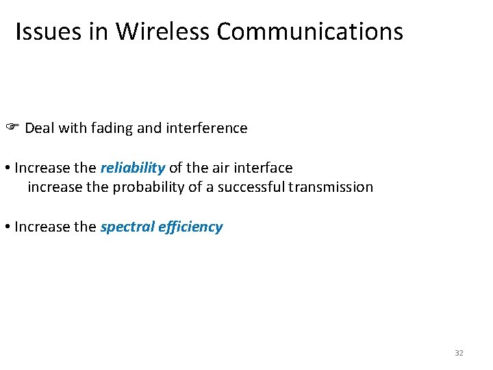
Issues in Wireless Communications Deal with fading and interference • Increase the reliability of the air interface increase the probability of a successful transmission • Increase the spectral efficiency 32
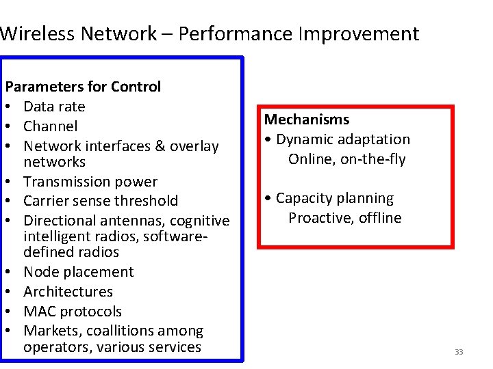
Wireless Network – Performance Improvement Parameters for Control • Data rate • Channel • Network interfaces & overlay networks • Transmission power • Carrier sense threshold • Directional antennas, cognitive intelligent radios, softwaredefined radios • Node placement • Architectures • MAC protocols • Markets, coallitions among operators, various services Mechanisms • Dynamic adaptation Online, on-the-fly • Capacity planning Proactive, offline 33
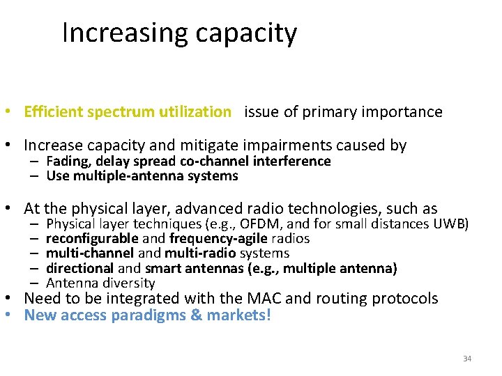
Increasing capacity • Efficient spectrum utilization issue of primary importance • Increase capacity and mitigate impairments caused by – Fading, delay spread co-channel interference – Use multiple-antenna systems • At the physical layer, advanced radio technologies, such as – – – Physical layer techniques (e. g. , OFDM, and for small distances UWB) reconfigurable and frequency-agile radios multi-channel and multi-radio systems directional and smart antennas (e. g. , multiple antenna) Antenna diversity • Need to be integrated with the MAC and routing protocols • New access paradigms & markets! 34
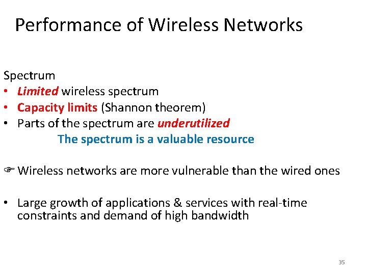
Performance of Wireless Networks Spectrum • Limited wireless spectrum • Capacity limits (Shannon theorem) • Parts of the spectrum are underutilized The spectrum is a valuable resource Wireless networks are more vulnerable than the wired ones • Large growth of applications & services with real-time constraints and demand of high bandwidth 35
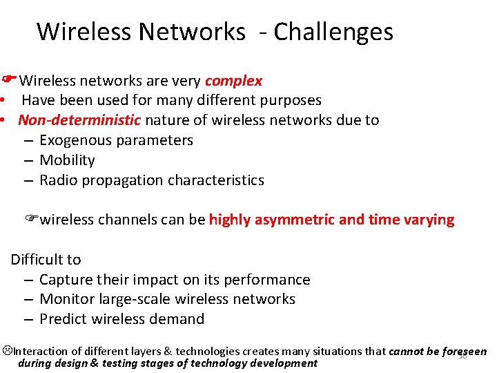
Wireless Networks - Challenges Wireless networks are very complex • Have been used for many different purposes • Non-deterministic nature of wireless networks due to – Exogenous parameters – Mobility – Radio propagation characteristics wireless channels can be highly asymmetric and time varying Difficult to – Capture their impact on its performance – Monitor large-scale wireless networks – Predict wireless demand Interaction of different layers & technologies creates many situations that cannot be foreseen 36 during design & testing stages of technology development
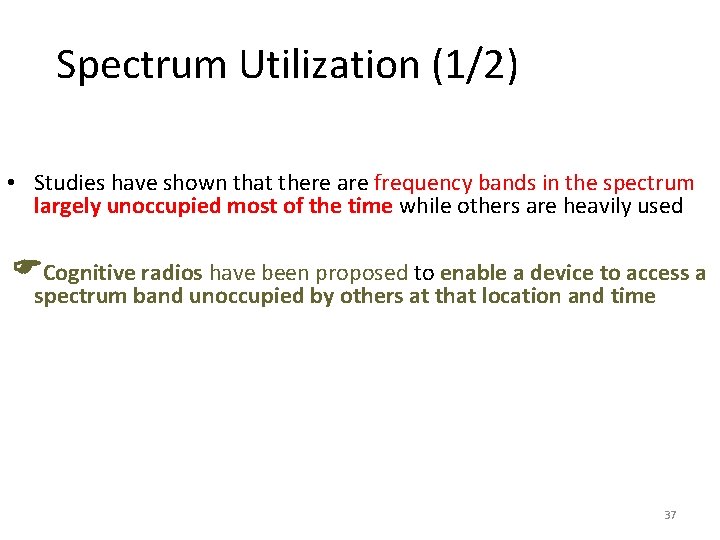
Spectrum Utilization (1/2) • Studies have shown that there are frequency bands in the spectrum largely unoccupied most of the time while others are heavily used Cognitive radios have been proposed to enable a device to access a spectrum band unoccupied by others at that location and time 37
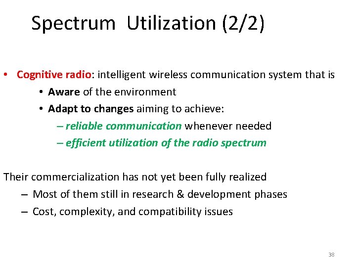
Spectrum Utilization (2/2) • Cognitive radio: intelligent wireless communication system that is • Aware of the environment • Adapt to changes aiming to achieve: – reliable communication whenever needed – efficient utilization of the radio spectrum Their commercialization has not yet been fully realized – Most of them still in research & development phases – Cost, complexity, and compatibility issues 38
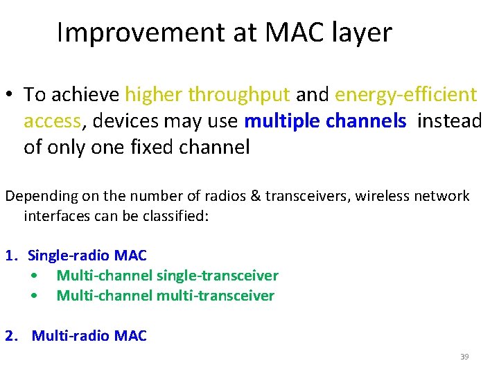
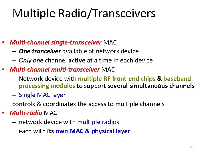
Improvement at MAC layer • To achieve higher throughput and energy-efficient access, devices may use multiple channels instead of only one fixed channel Depending on the number of radios & transceivers, wireless network interfaces can be classified: 1. Single-radio MAC • Multi-channel single-transceiver • Multi-channel multi-transceiver 2. Multi-radio MAC 39
Multiple Radio/Transceivers • Multi-channel single-transceiver MAC – One tranceiver available at network device – Only one channel active at a time in each device • Multi-channel multi-transceiver MAC – Network device with multiple RF front-end chips & baseband processing modules to support several simultaneous channels – Single MAC layer controls & coordinates the access to multiple channels • Multi-radio MAC – network device with multiple radios each with its own MAC & physical layer 40
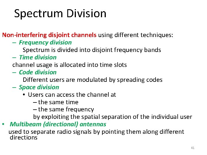
Spectrum Division Non-interfering disjoint channels using different techniques: – Frequency division Spectrum is divided into disjoint frequency bands – Time division channel usage is allocated into time slots – Code division Different users are modulated by spreading codes – Space division • Users can access the channel at – the same time – the same frequency by exploiting the spatial separation of the individual user • Multibeam (directional) antennas used to separate radio signals by pointing them along different directions 41
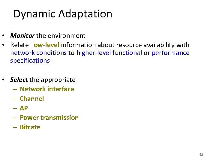
Dynamic Adaptation • Monitor the environment • Relate low-level information about resource availability with network conditions to higher-level functional or performance specifications • Select the appropriate – Network interface – Channel – AP – Power transmission – Bitrate 42
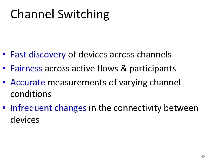
Channel Switching • Fast discovery of devices across channels • Fairness across active flows & participants • Accurate measurements of varying channel conditions • Infrequent changes in the connectivity between devices 43
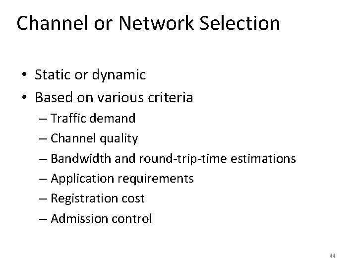
Channel or Network Selection • Static or dynamic • Based on various criteria – Traffic demand – Channel quality – Bandwidth and round-trip-time estimations – Application requirements – Registration cost – Admission control 44
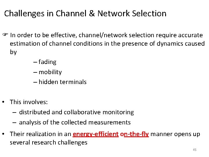
Challenges in Channel & Network Selection In order to be effective, channel/network selection require accurate estimation of channel conditions in the presence of dynamics caused by – fading – mobility – hidden terminals • This involves: – distributed and collaborative monitoring – analysis of the collected measurements • Their realization in an energy-efficient on-the-fly manner opens up several research challenges 45
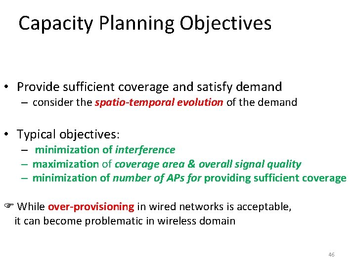
Capacity Planning Objectives • Provide sufficient coverage and satisfy demand – consider the spatio-temporal evolution of the demand • Typical objectives: – minimization of interference – maximization of coverage area & overall signal quality – minimization of number of APs for providing sufficient coverage While over-provisioning in wired networks is acceptable, it can become problematic in wireless domain 46
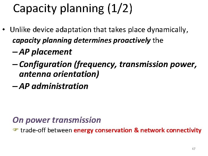
Capacity planning (1/2) • Unlike device adaptation that takes place dynamically, capacity planning determines proactively the – AP placement – Configuration (frequency, transmission power, antenna orientation) – AP administration On power transmission trade-off between energy conservation & network connectivity 47
Capacity Planning: Power Control • Reducing transmission power, lowers the interference – Reduces • Number of collisions • Packet retransimissions due to interference – Results in a • Smaller number of communication links • Lower connectivity trade-off between energy conservation & network connectivity 48
Power Control • Integral component of capacity planning • Aims to control spectrum spatial reuse, connectivity, and interference • Adjust the transmit power of devices, such that their SINR meets a certain threshold required for an acceptable performance 49
Connectivity Problems • Reflect lack of sufficient wireless coverage • An end user may observe degraded performance – e. g. , low throughput or high latency due to: – Wired or wireless parts of the network – Congestion in different networking components – Slow servers 50
Roaming (1/2) Handoff between APs and across subnets in wireless LANs can consume from one to multiple seconds as associations and bindings at various layers need to be re-established Examples of sources of delay include – Acquiring new IP addresses, with duplicate address detection – Re-establishing associations – Discovering possible APs • Without scanning the whole frequency range 51
Roaming (2/2) The scanning in a handoff – Primary contributor to the overall handoff latency – Can affect the quality of service for many applications – Can be 250 ms or more – Far longer than what can be tolerated by highly interactive applications (i. e. voice telephony) 52
Security Issues • Involve the presence of rogue APs & malicious clients • In mobile wireless networks, it is easier to – disseminate worms, viruses, false information – eavesdrop – deploy rogue or malicious software or hardware – attack, or behave in a selfish or malicious manner • Attacks may – occur @ different layers aiming to exhaust the resources – promise falsely to relay packets – not respond to requests for service 53
Monitoring • Depending on type of conditions that need to be measured, monitoring needs to be performed at • Certain layers • Spatio-temporal granularities • Monitoring tools – Are not without flaws – Several issues arise when they are used in parallel for thousands devices of different types & manufacturers: • Fine-grain data sampling • Time synchronization • Incomplete information • Data consistency 54
Issues in Data Collection 1. Synchronization • Skew of the clocks – affected via various external parameters e. g. , temperature, voltage, electromagnetic interference • Synchronization can be done using Network Time Protocol (NTP) & Precision Time Protocol (PTP) 2. Data Consistency Differences in how various monitoring tools record the data 3. Incomplete information Monitoring tools fail to capture different parameters due to misconfigurations, failures, limited functionality 55
Challenges in Monitoring (1/2) • Identification of the dominant parameters through – sensitivity analysis studies • Strategic placement of monitors at – Routers – APs, clients, and other devices • Automation of the monitoring process to reduce human intervention in managing the • Monitors • Collecting data 56
Challenges in Monitoring (2/2) • Aggregation of data collected from distributed monitors to improve the accuracy while maintaining low overhead in terms of • Communication • Energy • Cross-layer measurements, collected data spanning from the physical layer up to the application layer, are required 57