1 RF transceiver EMLAB Block diagram of wireless

1 RF transceiver EMLAB

Block diagram of wireless transmitter 2 EMLAB

Block diagram of wireless receiver 3 EMLAB

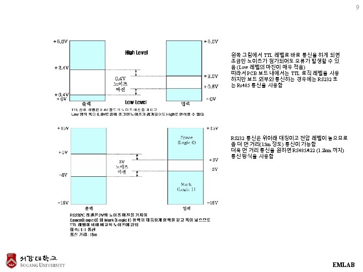
RS 232 C 4 EMLAB

5 EMLAB

6 EMLAB

Rs 232 oscilloscope trace 7 EMLAB

Rs 232 waveforms 8 This is the instruction bytes. Note that the voltage swing of the instruction waveform is about +/-10 V. This is typical of the USB to RS 232 converter to which the device is connected This is a closeup of the instruction byte 2. The "S" on either end represents the start and stop bits respectively. The start bit is always positive and the stop bit is always negative. The bit sequence is Start, 0, 1, 2, 3, 4, 5, 6, 7, Stop. The data is output with the least significant bit first, so the byte shown is actually 0011 in binary or 32+16+2+1 = 51 in decimal. EMLAB

10 EMLAB

11 EMLAB

RS 485 12 EMLAB

RF module 13 http: //extremeelectronics. co. in/avr-tutorials/rf-communication-between -microcontrollers-part-ii/ EMLAB

14 EMLAB

RF transceiver example 15 EMLAB

Function 16 EMLAB

17 EMLAB

18 EMLAB

19 EMLAB

20 EMLAB

21 EMLAB

22 EMLAB

RF module firmware 23 EMLAB

24 EMLAB

25 EMLAB

26 EMLAB

27 EMLAB

28 EMLAB

30 EMLAB

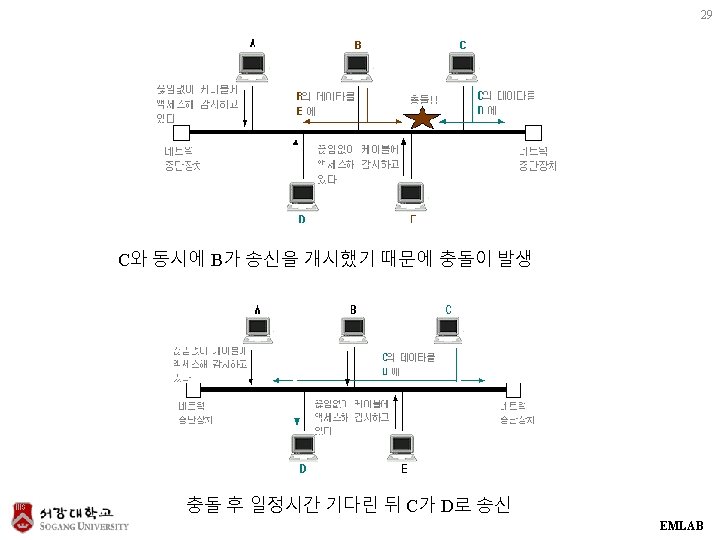
CSMA protocol 31 EMLAB

Example : MCU 32 EMLAB

33 EMLAB

34 EMLAB

35 EMLAB

36 EMLAB
- Slides: 36