Overview of the ILC overview of GDE activities


- Slides: 33

Overview of the ILC (overview of GDE activities) Nick Walker (DESY/GDE) ILC-Hi. Grade Kick-Off Meeting 28. 08. 2008

Historical Background • Over 15 years active international R&D 2001 – NLC/JLC based on Cu x-band technology (11. 4 GHz) – CLIC two-beam accelerator (30 GHz) – TESLA Superconducting RF (SCRF, 1. 3 GHz) 2006 • 2002 German BMBF XFEL decision – Request to internationalize effort • 2004 ITRP recommends SCRF Linac Technology for the ILC – Recommendation later endorsed by ICFA • 2005 Global Design Effort (GDE) Formed 2

ILC GDE: A Truly Global Effort EU US Asia Joint Design, Implementation, Operations, Management Host Country Provides Conventional Facilities Global Design Effort 3

Global Design Effort 2001 • 2005: Formation of the GDE by ICFA – Barry Barish – director • History – Dec 2005 - Definition of baseline design – Dec 2006 - Completion of conceptual design with cost estimate (including first iteration cost reduction) – Jul 2007 – Publication of 4 -volume Reference Design Report (RDR). – 2008 - restructuring for Technical Design Phase 2006 2007 4

ILC Requirements • Ecm adjustable from 200 – 500 Ge. V • Luminosity: ∫Ldt = 500 fb-1 in 4 years ILCSC Parameters group – Peak at max. energy of 2× 1034 cm-2 s-1 – Assume 1/g L scaling for <500 Ge. V • • Energy stability and precision below 0. 1% Electron polarization of at least 80% The machine must be upgradeable to 1 Te. V Two detectors – Single IR in push-pull configuration – Detector change-over in not more than 1 week 5

The ILC Reference Design ~31 km • 200 -500 Ge. V centre-of-mass • Luminosity: 2× 1034 cm-2 s-1 • Based on accelerating gradient of 31. 5 MV/m (1. 3 GHz SCRF) 6

ILC Reference Design • • • High-gradient R&D Industrialisation Mass-production 7

Cost (VALUE) Estimate • Estimated cost (2007) ~6. 7 Billion ILCU* – 4. 87 BILCU shared – 1. 78 BILCU site-specific • 10, 000 person-years “implicit” labour 8

The GDE Post-RDR • Publication of the RDR was a major milestone • Analysis of the RDR design/cost priorities for Technical Design Phase • Re-structuring of GDE into a more traditional Project Structure – Hierarchal org. chart – Project Management Team • Ross, Walker, Yamamoto • Focus of TDP work: – Risk mitigating R&D – Overall Cost Reduction / Containment (optimisation) – Project Implementation Plan (PIP) 9

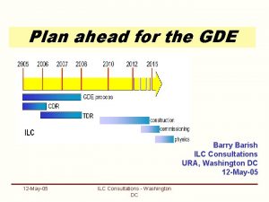
GDE Time Line until 2012 2005 2006 2007 2008 2009 2010 2011 2012 2013 GDE process Reference Design Report (RDR) Tech. Design Phase (TDP) 1 TDP 2 ILC-Hi. Grade Ready for Project Submission LHC physics

GDE Time Line until 2012 2005 2006 2007 2008 2009 2010 2011 2012 2013 GDE process Reference Design Report (RDR) Tech. Design Phase (TDP) 1 TDP 2 ILC-Hi. Grade Submission to international funding authorities/agencies - Updated technical design - Updated VALUE estimate - Project Implementation Plan - (Updated physics case [LHC]) Ready for Project Submission LHC physics

TD Phase Project Structure Project structure focused on RDR Cost-Drivers (Technical Areas) 12

TD Phase Project Structure 13

A Global R&D Plan • Available from: http: //ilcedmsdirect. desy. de/ilcedmsdirect/file. jsp? edmsid=D 0000*813385 • • First Official Release Next review and release: December 08 • Contains summary of Global Resources available for ILC-related activites. 14

TD Phase Priorities SCRF gradient R&D Reduction of underground volume Better systems integration Reduced overhead / conservatism … Cost Reduction R&D for Technical Risk Mitigation R&D based at Test Beam Facilities - Japan (ATF, ATF-2 at KEK) - US (CESR-TA at Cornell) Project Implementation Plan ILC International Project Proposal (2012) International governance Funding Siting Mass production models … Global Mass Production Models and Industrialisation SCRF Linac components -Cavities -Cryomodules -Klystrons -… 15

Technical Phase Roadmap Global Design Effort

Technical Phase I Roadmap Global Design Effort

Technical Phase II Roadmap • Development of “plug compatible” linac components considered critical for global mass-production models • XFEL (European) planned CM mass-production (in-kind contribution scheme). Global Design Effort

PM TD Phase 1 & 2 Schedule • A tentative top-level management plan for TD Phase 1 & 2 now exists – Published in R&D Plan – More detailed schedule being updated • MS Project • Part of release 2 • Encapsulates the PMs strategy and vision for the next four years – Critical R&D – Cost reduction / machine design – Project Implementation Plan

SCRF Cavity Gradient • R&D priority – very high – RDR estimate: 10% improvement in gradient reduce ILC cost by 7% • Goal: Determine production yield at nominal (35 MV/m) gradient – TDP 1 Goal: 35 MV/m 50% yield – TDP 2 Goal: 35 MV/m 80% yield • Progress since technology choice (08/2004): – – (Primarily at DESY; also J-Lab and KEK) 2006: 50% yield 27. 5 MV/m 2008: 50% yield 31. 5 MV/m each based on sample population of 15 nine cell cavities • Recent XFEL Industrial cavity pre-production series look very promising Global Design Effort

World-Wide Superconducting Cavities Global Design Effort

World-Wide Superconducting Cavities 808 XFEL production + ~30 ILC-High. Grade Global Design Effort

Global SCRF R&D (Examples) Major SCRF Infrastructure at FNAL (US) Single cell R&D at KEK TTF at DESY European XFEL at DESY Cryomodule Development at KEK 23

Reducing the COST

Cost Reduction: A Strategy • Required engineering resources will be very limited in TD Phase 1 • Use time to take a fresh look at RDR design – Perform design/performance iterations that were not completed in RDR phase • Approach – Re-evaluate RDR design with a strong emphasis on COST drivers – Specifically, focus on machine layout which could reduce the use of underground volume cost driver – Push back on conservatism in Conventional Facilities (i. e. processed water cooling, electrical power etc. ) cost driver – Evaluate possible shallow site solutions • As a study tool, develop concept of the Minimum Machine Global Design Effort

The Minimum Machine Study Aim for here Margin, risk reduction, redundancy, … (indirect performance) cost Is the RDR here? 500 Ge. V 2 1034 cm-2 s-1 Physics “figure of Merit” (direct performance) Minimum Machine Understand the performance derivatives

Minimum Machine Concepts Ten – XFEL-like solution er d tative iscu – Surface klystron solutions ssio 2. Integration of e+/e- sources with upstream beam delivery n 1. Removal of service tunnel und system (same tunnel) – – 3. Main Linac - Novel high-power RF distribution – – – 4. 5. 6. 7. Move e+ undulator source to end of linac (250 Ge. V point) e- source and 5 Ge. V injector linacs share BDS tunnel “klystron-clusters” on surface (30 klystrons/cluster) 300 MW “pipe” distribution over 1 km using over-moded waveguide (single tunnel solution) Main Linac – adoption of Marx modulator Reduced beam-power parameter set – – Half klystron/modulators 6 km 3 km damping ring – Mostly impacts BDS Potential cost savings primarily via reduced CFS requirements Two-stage single-stage bunch compressor Remove all support for Te. V upgrade 27

Minimum Machine Plan • TD Phase 1 – Develop ‘minimum machine’ description as alternative to RDR baseline – Develop list of issues / studies to evaluate MM comparison with RDR baseline for CY 2009 • Including cost saving – Early 2010 (end of TDP 1) evaluate MM studies and status of critical R&D (parallel), and – Agree on new formal reference design baseline for TD Phase 2 • TD Phase 2 – Engineering and updated value estimate based on adopted reference design 28

Project Implementation Plan 29

and the European… • From the ITRP Executive Summary (rationale for cold decision) 2004: – “The construction of the superconducting XFEL free electron laser will provide prototypes and test many aspects of the linac. – The industrialization of most major components of the linac is underway. ” • The European XFEL is Europe’s dominant contribution to the ILC 30

ILC and the European XFEL • XFEL will mass-produce, install and commission 101 SCRF cryomodules from end 2009 until end 2012. – Very similar to ILC cryomodules • 808 cavities, HP couplers, tuners etc. – Operational cavity gradient requirement lower for XFEL • XFEL 23. 5 MV/m • ILC 31. 5 MV/m – An important systems test for ILC • XFEL as international “in-kind contribution” project – Linac technology supplied by collaboration of Germany (DESY), France (SACLAY, LAL), Italy (INFN), Spain (CIEMAT), Poland. – Important experience for International Project Implementation Plan for ILC 31

GDE ILC and XFEL Timeline 2005 2006 2007 2008 2009 2010 2011 2012 2013 GDE process Reference Design Report (RDR) Tech. Design Phase (TDP) 1 TDP 2 LHC physics XFEL R&D Ready for Project Submission XFEL preparatory engineering XFEL civil construction XFEL cryomodule production FIRST BEAM 32

In Summary • In a truly (perhaps unique) global collaboration, the GDE has successfully produce a design for the ILC and an associated cost estimate – Based on a mature linac technology – A “low risk” design • The GDE is now planning a ‘Technical Design Phase’ which will – – Consolidate the design and reduce the cost Complete risk-mitigating R&D Ramp-up SCRF facilities and expertise and Americas and Asian regions Produce a realistic Project Implementation Plan • Together with FALC • The European XFEL will provide a significant ILC resource! – Industrialisation / mass production infrastructure – Systems tests (10% ILC linac prototype) – Iin-kind contribution model • Ready for project approval in 2012 33
 Spectrum ilc 1002
 Ilc 150 eth
 David i
 Ilc dover space suit
 Zora rutar ilc
 Ilc and slc
 Ilc brno
 Ilc 2013
 Primary and support activities
 Examples of primary activities
 Operating activities vs investing activities
 Outdoor sports name
 Gde je nastao samov savez
 Feliks salten
 Gde status
 Avtor bambija feliks
 Gde vision and mission
 Que es el gde
 Ravnica u srbiji
 Global digital exemplars
 Gde kupiti menicu
 Podrinjske planine
 Eno gde leti cvet analiza
 Dubai se nalazi na kontinentu
 Ekurhuleni north district exam papers
 Dokumenta u osiguranju
 Na kom kontinentu se nalazi egipat
 Inflacija traznje
 Flexura coli dextra
 Gde status
 Kupule
 Backa ravnica menu
 Gde strategic goals
 Gde zameniti stare funte
