OPA 454 Analysis Tim Green MGTS Precision Op
- Slides: 27
OPA 454 Analysis Tim Green, MGTS Precision Op Amp Applications Manager November 5, 2018 1
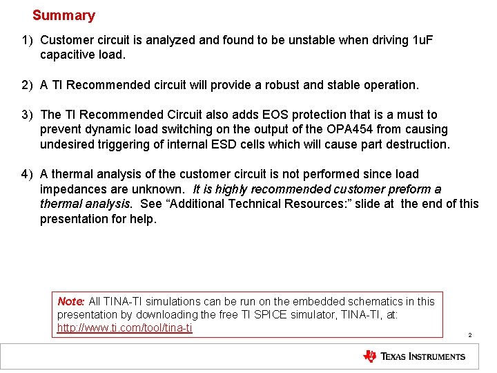
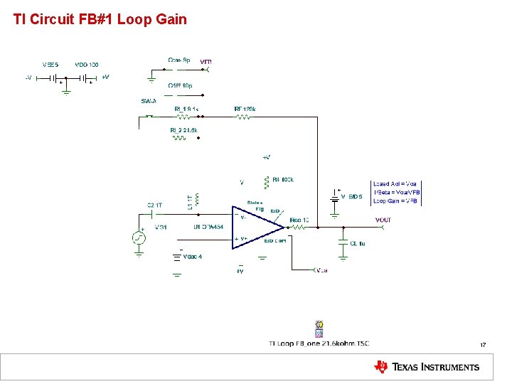
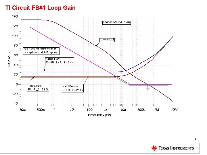
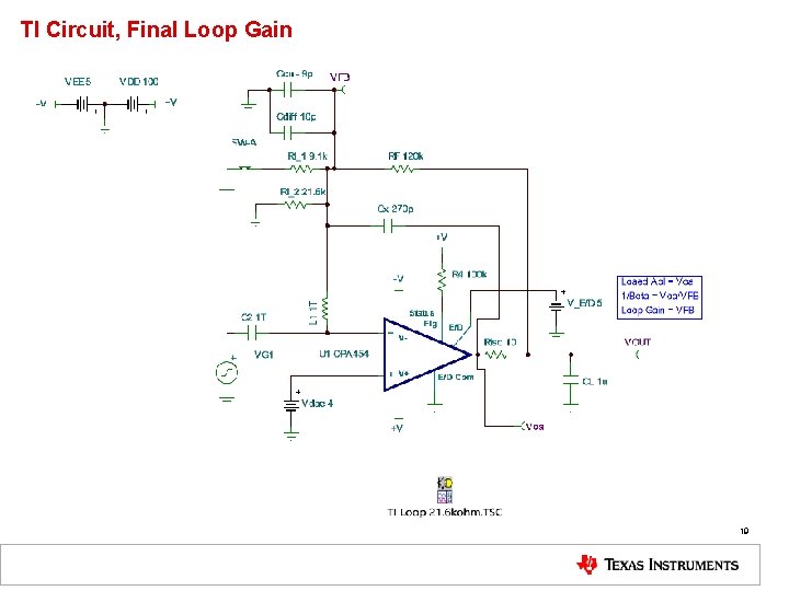
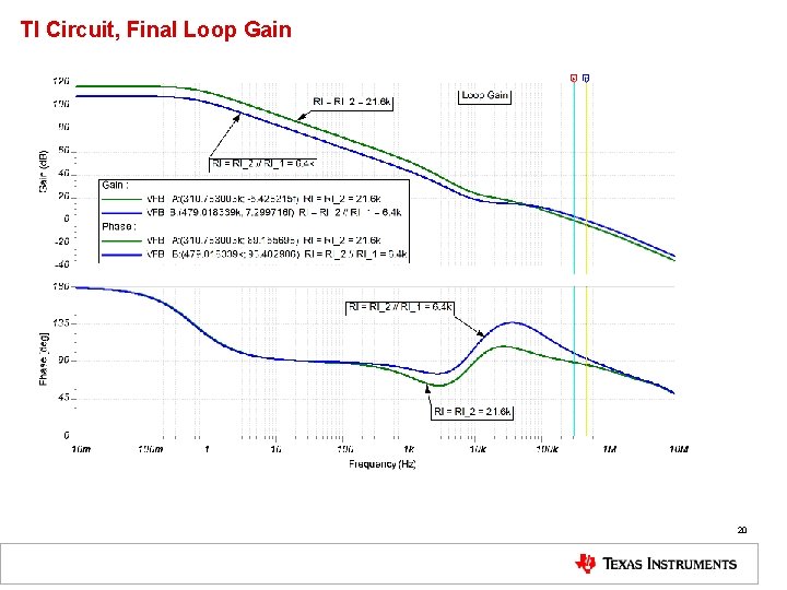
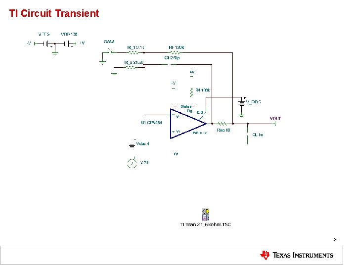
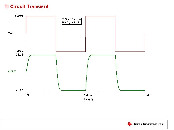
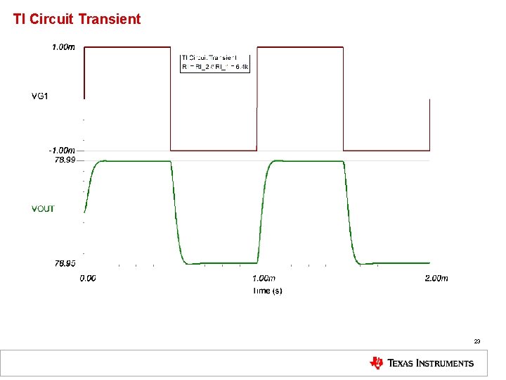
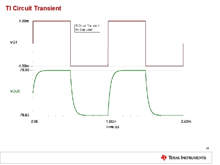
Summary 1) Customer circuit is analyzed and found to be unstable when driving 1 u. F capacitive load. 2) A TI Recommended circuit will provide a robust and stable operation. 3) The TI Recommended Circuit also adds EOS protection that is a must to prevent dynamic load switching on the output of the OPA 454 from causing undesired triggering of internal ESD cells which will cause part destruction. 4) A thermal analysis of the customer circuit is not performed since load impedances are unknown. It is highly recommended customer preform a thermal analysis. See “Additional Technical Resources: ” slide at the end of this presentation for help. Note: All TINA-TI simulations can be run on the embedded schematics in this presentation by downloading the free TI SPICE simulator, TINA-TI, at: http: //www. ti. com/tool/tina-ti 2
Customer Inputs 3
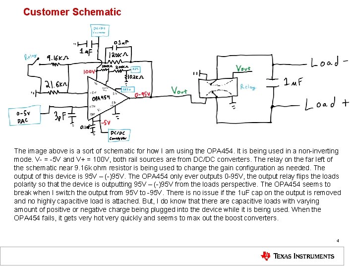
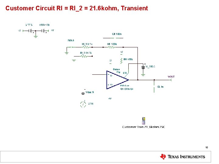
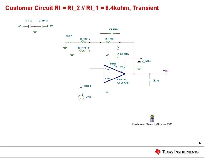
Customer Schematic The image above is a sort of schematic for how I am using the OPA 454. It is being used in a non-inverting mode. V- = -5 V and V+ = 100 V, both rail sources are from DC/DC converters. The relay on the far left of the schematic near 9. 16 k ohm resistor is being used to change the gain configuration as needed. The output of this device is 95 V – (-)95 V. The OPA 454 only ever outputs 0 -95 V, the output relay flips the loads polarity so that the device is outputting 95 V – (-)95 V from the loads perspective. The OPA 454 seems to break when I switch the output from 95 V to -95 V. There is no issue if the 1 u. F cap on the output is removed and no highly capacitive load is attached. But, I do know that there are capacitive loads with varying amount of positive or negative charge being plugged into the device while it is being used. When the OPA 454 fails, it gets very hot very quickly and seems to max out the boost converters. 4
Customer Circuit Analysis 5
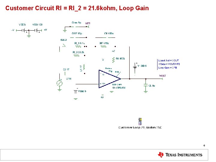
Customer Circuit RI = RI_2 = 21. 6 kohm, Loop Gain 6
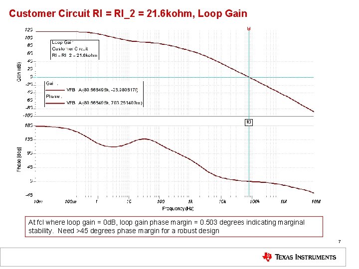
Customer Circuit RI = RI_2 = 21. 6 kohm, Loop Gain At fcl where loop gain = 0 d. B, loop gain phase margin = 0. 503 degrees indicating marginal stability. Need >45 degrees phase margin for a robust design 7
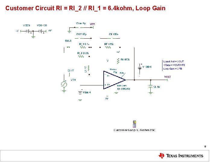
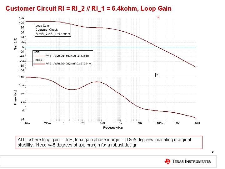
Customer Circuit RI = RI_2 // RI_1 = 6. 4 kohm, Loop Gain 8
Customer Circuit RI = RI_2 // RI_1 = 6. 4 kohm, Loop Gain At fcl where loop gain = 0 d. B, loop gain phase margin = 0. 856 degrees indicating marginal stability. Need >45 degrees phase margin for a robust design 9
Customer Circuit RI = RI_2 = 21. 6 kohm, Transient 10
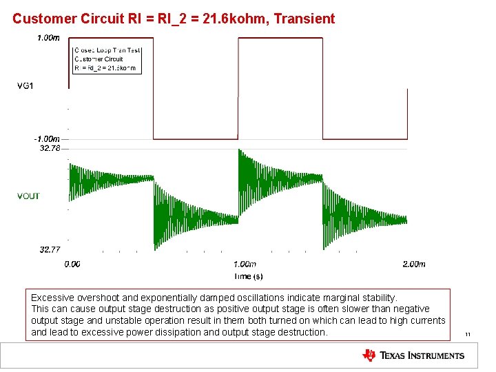
Customer Circuit RI = RI_2 = 21. 6 kohm, Transient Excessive overshoot and exponentially damped oscillations indicate marginal stability. This can cause output stage destruction as positive output stage is often slower than negative output stage and unstable operation result in them both turned on which can lead to high currents and lead to excessive power dissipation and output stage destruction. 11
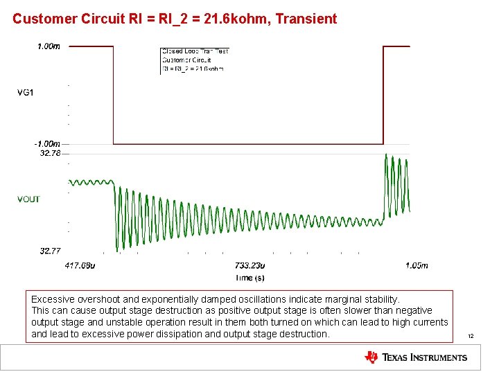
Customer Circuit RI = RI_2 = 21. 6 kohm, Transient Excessive overshoot and exponentially damped oscillations indicate marginal stability. This can cause output stage destruction as positive output stage is often slower than negative output stage and unstable operation result in them both turned on which can lead to high currents and lead to excessive power dissipation and output stage destruction. 12
Customer Circuit RI = RI_2 // RI_1 = 6. 4 kohm, Transient 13
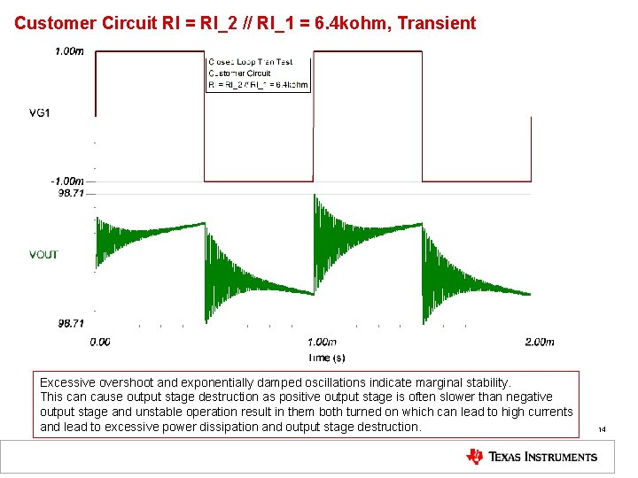
Customer Circuit RI = RI_2 // RI_1 = 6. 4 kohm, Transient Excessive overshoot and exponentially damped oscillations indicate marginal stability. This can cause output stage destruction as positive output stage is often slower than negative output stage and unstable operation result in them both turned on which can lead to high currents and lead to excessive power dissipation and output stage destruction. 14
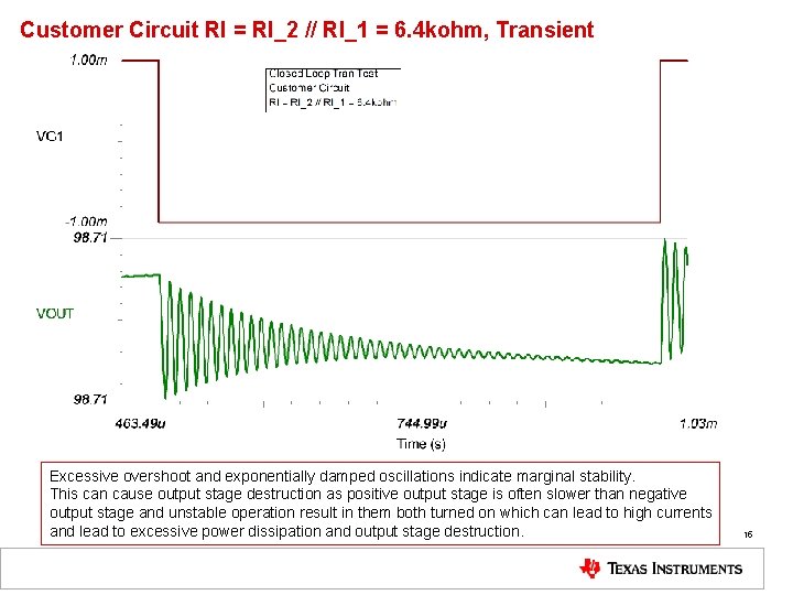
Customer Circuit RI = RI_2 // RI_1 = 6. 4 kohm, Transient Excessive overshoot and exponentially damped oscillations indicate marginal stability. This can cause output stage destruction as positive output stage is often slower than negative output stage and unstable operation result in them both turned on which can lead to high currents and lead to excessive power dissipation and output stage destruction. 15
TI Recommended Circuit Analysis 16
TI Circuit FB#1 Loop Gain 17
TI Circuit FB#1 Loop Gain 18
TI Circuit, Final Loop Gain 19
TI Circuit, Final Loop Gain 20
TI Circuit Transient 21
TI Circuit Transient 22
TI Circuit Transient 23
TI Circuit Transient 24
TI Recommended Circuit Analysis EOS (Electrical Over. Stress) Protection 25
TI Recommended EOS Protection 26
Additional Technical Resources Op Amp Stability: https: //e 2 e. ti. com/support/amplifiers/f/14/t/735210? tisearch=e 2 e-sitesearch&keymatch=faq%3 Atrue Electrical Over. Stress (EOS): https: //training. ti. com/ti-precision-labs-op-amps 12. TI Precision Labs - Op Amps: Electrical Overstress (EOS) Op Amp Thermal Considerations: https: //training. ti. com/ti-precision-labs-op-amps 4. TI Precision Labs - Op Amps: Power and Temperature 27 of 74