Nonideal property crosstalk 1 Far end crosstalk voltage


 i (z+ z, t) + L")


 for short")


 Network for z. L inside")


 1+jb 원의 원주 상의 지점을 shunt stub(병 렬 stub)을")
 (b) The two shunt-stub tuning solutions. (c)")
- Slides: 36
Non-ideal property – crosstalk 1 인접한 전선들 사이에 간섭이 생긴다. Far end crosstalk voltage Voltage Near end crosstalk voltage EMLAB
Types of transmission lines 2 Microstrip line Coaxial cable Two-wire transmission line EMLAB
Transmission line parameter - examples 3 Coax a b Parallel Plate W d EMLAB
4 Parallel wire a + D - Coplanar waveguide EMLAB
Transmission line 등가 회로 5 i (z, t) i (z+ z, t) + L z v (z, t) - + v (z, t) z + C z v (z+ z, t) - z EMLAB
Transmission line eq. solution 6 EMLAB
Reflection coefficient 7 + V - EMLAB
Influence of line length on load voltage 8 Impedance mismatched + V - Vin Vt. Pulse SRC 1 Vout R R 1 R=20 Ohm MLIN R R 2 R=1 k Ohm + V - t Z 0= 50 Zs = 20 + V - Z 0= 50 ZL= 1 k + V - 0. 5 m + V - EMLAB
Line 길이에 따른 수신 신호 9 Impedance matched + V - Vin R Vt. Pulse R 1 SRC 1 R=50 Ohm Vout MLIN R R 2 R=50 Ohm t + V - Z 0= 50 Zs = 1 + V - Z 0= 50 ZL= 50 + V - 0. 5 m + V - EMLAB
Ringing 10 ~ Signal source Load Mismatched load EMLAB
Impedance matching - Digital 11 Source matching ~ ~ Load matching EMLAB
Narrow band signal 12 Typical time domain waveforms Spectrum Fractional bandwidth EMLAB
Frequency domain solution 13 β : propagation constant, vp : speed of light EMLAB
Phasor representation 14 + V - EMLAB
Transmission line terminated with short, open 15 Out of phase (180◦ ) for short Vinc Vrefl short open In phase (0 ◦) for open Vrefl For reflection, a transmission line terminated in a short or open reflects all power back to source EMLAB
Transmission Line Terminated with 25 Ω V inc 16 Vrefl Standing wave pattern does not go to zero as with short or open. EMLAB
17 Standing wave of free end Open circuit Standing wave of fixed end Short circuit Standing waves of harmonics EMLAB
Equivalent input impedance 18 EMLAB
Input impedance of short 19 EMLAB
Input impedance of open 20 EMLAB
Input impedance of ¼ wavelength line 21 Quarter wavelength transformer EMLAB
Reflection measurement – slotted line 22 Standing wave ratio EMLAB
Network analyzer 24 EMLAB
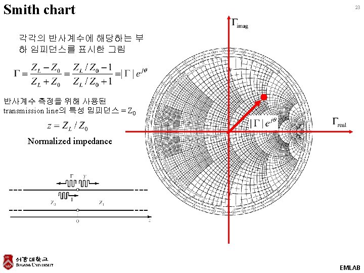
Smith chart review 25 Z-plane +j. X 90 Z-to-Γ transform o Polar plane 1. 0. 8 0 . 6 +R ¥ ® -j. X . 4 + 180 o - . 2 0 o ¥ 0 -90 o Rectilinear impedance plane Constant X Smith Chart maps rectilinear impedance plane onto polar plane Z L = Zo G= 0 Z L = 0 (short) G= 1 Constant R ± 180 O Z L= G =1 (open) 0 O Smith Chart EMLAB
Constant resistance, reactance circles 26 x r=0. 5 r=1 0 0. 5 1 r=2 R 2 x=0. 5 x=1 1 x=2 0. 5 R 1 x=-2 x=-1 2 x=-0. 5 EMLAB
Constant admittance circles 27 Y-plane +j. B 0 +j. G Z-plane +j. X 0 -j. X EMLAB
Basic Smith chart operation 28 1. Translation 2. Add series element L C EMLAB
29 3. Add shunt element L C EMLAB
Matching with lumped elements 30 L-section matching networks. (a) Network for z. L inside the 1 + jx circle. (b) Network for z. L outside the 1 + jx circle. EMLAB
Example 5. 1 31 Smith chart – impedance chart Figure 5. 3 a (p. 226) Solution to Example 5. 1. (a) Smith chart for the L-section matching networks. 3 ZL= 200 -j 100 Z 0= 100 f = 500 MHz 2 5 1 4 EMLAB
32 Impedance-admittance chart ZL= 200 -j 100 Z 0= 100 f = 500 MHz 0. 0 1 0. 2 Add series L Add shunt C 0. 5 1. 2 EMLAB
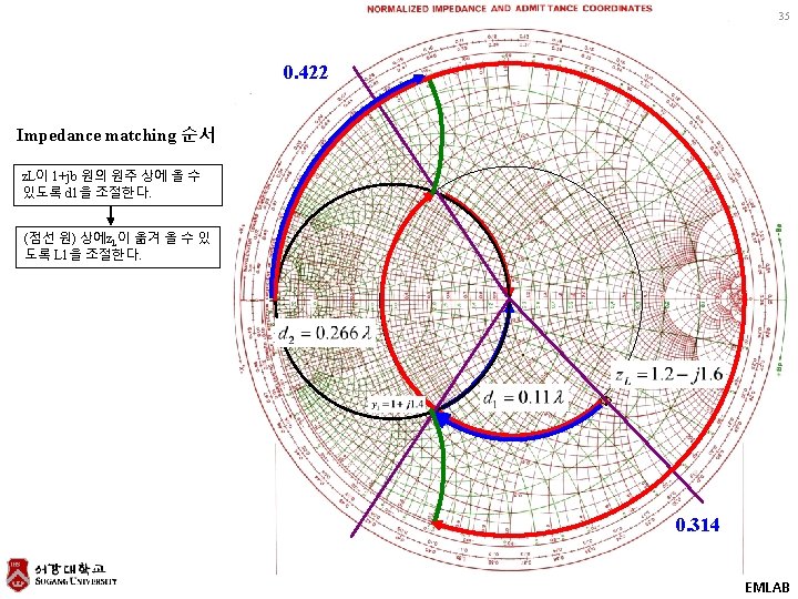
Single stub tuning 33 ZL= 60 -j 80 Z 0= 50 f = 2 GHz Translate by ‘d’ 1 1 0. 314 0. 422 0. 31 4 D를 변화시켜 1+jb 원의 원주 상에 y. L이 오도록 한다. EMLAB
34 Add shunt stub (shorted) 1+jb 원의 원주 상의 지점을 shunt stub(병 렬 stub)을 달아서 Γ원의 원점으로 옮기 면 impedance matching이 완료됨. EMLAB
36 Figure 5. 5 b (p. 231) (b) The two shunt-stub tuning solutions. (c) Reflection coefficient magnitudes versus frequency for the tuning circuits of (b). EMLAB